


Installing and Setting Up the Unit
6
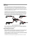
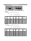
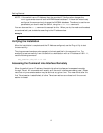
1 Global LEDs
PWR Green ON indicates Power ON
MGMT Blinking Green indicates that the firmware is initializing
Solid Green indicates that firmware is installed and in
proper operational mode
2 10/100 Port LEDs
L
Solid Green indicates a valid connection. During LINK
test, there is an intermittent flash on all the ports.
A Solid Green indicates network activity.
3 10/100 Base-T ports
One of three groups of switched Ethernet ports for
10/100Mbps connection
4 DB-9 Connector
RS-232 connection for NMS
5 Optional Module LEDs
6
Optional Module
Port/s
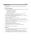
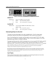
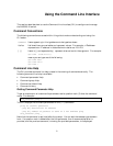
Rear Panel
The rear panel of the NH2025-10, which houses the power connection and ON/OFF switch, is
illustrated in Figure 4. Two fan holes, which MUST be kept unobstructed, are located on the
left side of the unit.
Figure 4 - Rear Panel
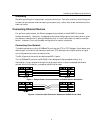
Installing Modules in the Unit
To insure proper installation, complete the following:
1. Power OFF the NH2025-10 switch.
2. Carefully slide an NH2025-10 module into a free dport and press firmly to insert.
3. Tighten the thumbscrews securely.
4. Power ON the NH2025-10 switch. If you have a flash version lower than 1.20 and you are
installing F/O modules, you must download a new software version to the switch so that the
firmware recognizes the new uplinks and the modules operate correctly.