


4. Remove the filler module from the selected bay. Store the filler module for
future use.
5. If you have not already done so, touch the static-protective package that
contains the GbE switch module to any unpainted metal surface of the
BladeCenter unit or any unpainted metal surface on any other grounded
rack-component for at least 2 seconds.
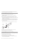
6. Remove the GbE switch module from its static-protective package.
7. Make sure that the release latch on the GbE switch module is in the open
position (perpendicular to the module).
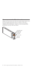
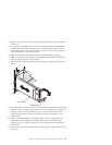
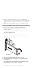
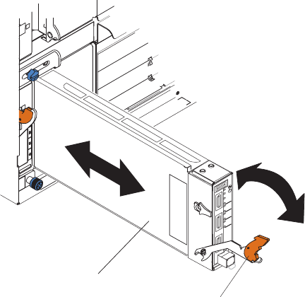
8. Slide the GbE switch module into the applicable I/O-module bay until it
stops.
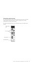
I/O module
Release latch
RS232
TX/RX
LINK
1
TX/RX
LINK
2
TX/RX
LINK
3
TX/RX
LINK
4
3
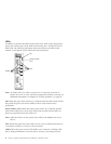
9. Push the release latch on the front of the GbE switch module to the closed
position. After you insert and lock the GbE switch module, it is turned on,
and the power-on self-test (POST) runs to verify that the GbE switch
module is operating correctly. The POST results are displayed by the
status LEDs.
10. Make sure that the LEDs on the GbE switch module indicate that it is
operating correctly. Make sure that the OK LED on each GbE switch
module is lit. See “LEDs” on page 6 for a description of the operation of
these LEDs.
11. If you have other GbE switch modules to install, do so now; otherwise, go
to step 12.
Chapter 2. Installing and removing the GbE switch module 11