


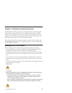
RS232
TX/RX
LINK
1
TX/RX
LINK
2
TX/RX
LINK
3
TX/RX
LINK
4
3
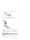
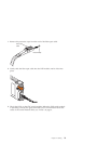
3. Check the LEDs on the GbE switch module. When the GbE switch module
is operating correctly, the green link LED is lit. For information about the
status of the switch module LEDs, see “LEDs” on page 6.
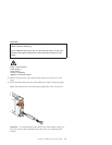
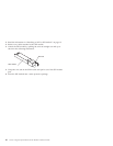
Disconnecting a CX4 module cable
To disconnect a CX4 cable, grasp the blue release tab on the cable connector
and firmly pull it out of the module.
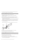
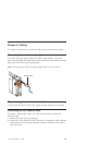
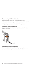
Connecting an XFP module cable
Attention: To avoid damage to the fiber-optic cables, follow these guidelines:
v Do not route the cable along a folding cable-management arm.
v When attaching the cable to a device on slide rails, leave enough slack in the
cable so that it does not bend to a radius of less than 38 mm (1.5 in.) when
the device is extended or become pinched when the device is retracted.
v Route the cable away from places where it can be snagged by other devices
in the rack.
v Do not overtighten the cable straps or bend the cables to a radius of less
than 38 mm (1.5 in.).
v Do not put excess weight on the cable at the connection point. Make sure
that the cable is well supported.
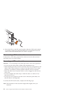
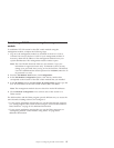
To connect the XFP module cable, complete the following steps:
Note: The illustrations in this document might differ slightly from your
hardware.
22 Nortel 10 Gigabit Uplink Ethernet Switch Module: Installation Guide