


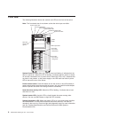
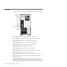
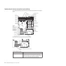
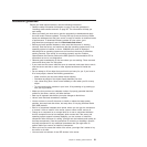
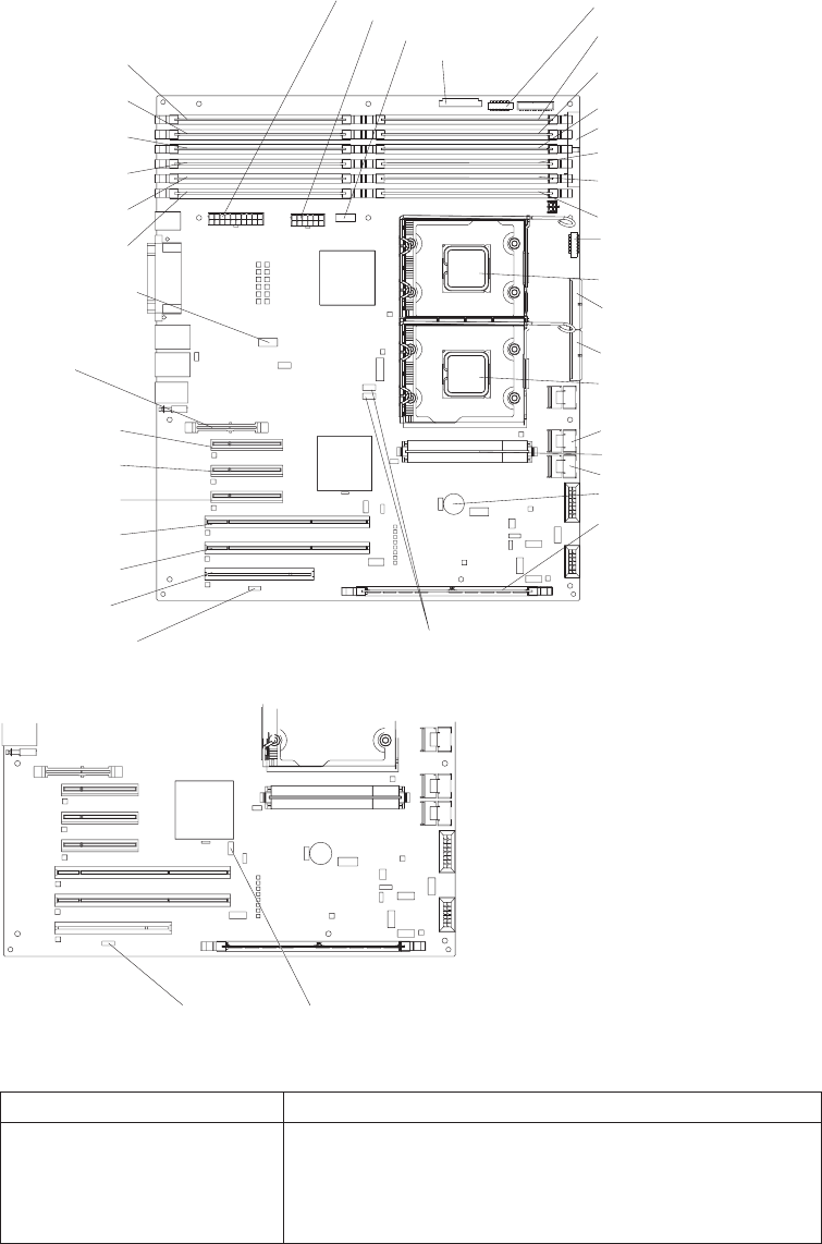
System-board internal connectors and switches
The following illustrations show the internal connectors and switches on the system
board.
DIMM 12
DIMM 6
DIMM 11
DIMM 5
DIMM 10
IDE
DIMM 4
DIMM 9
DIMM 3
DIMM 8
DIMM 2
DIMM 7
DIMM 1
Microprocessor 1
Microprocessor 2
VRM
Battery
ServeRAID-8k
PCI slot 6
PCI-X slot 5
PCI-X slot 4
PCI Express x8
with x8 links slot 1
PCI Express x8
with x8 links slot 2
PCI Express x8
with x8 links slot 3
Remote
Supervisor
Adapter
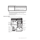
Power 1
Power 2
Power 3
Power switch
SAS 2
SAS 2 power
SAS 1
SAS 1 power
Rear fan
(optional)
Reserved
Front USB
Internal USB tape
Wake on LAN
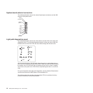
See Table 2 for information about the switch settings.
Wake on LAN
(CN 45)
SW4 (Boot block/Clear CMOS)
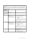
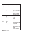
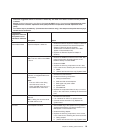
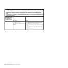
Table 2. Switches on SW4
Switch number Description
1 Boot block:
v Leave the switch in the off position for normal mode.
v Move the switch to the on position to enable the system
to recover if the BIOS code becomes damaged.
14 IBM System x3500 Type 7977: User’s Guide