


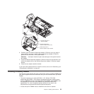
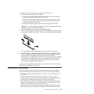
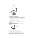
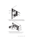
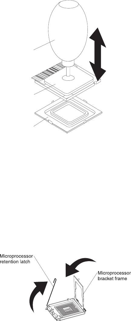
Vacuum tool
Microprocessor
Socket
a. Squeeze and hold the bladder of the tool; then, place the suction cup on
the microprocessor and release the bladder.
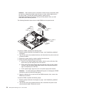
Note: To maintain proper orientation between the microprocessor and the
microprocessor socket during installation, observe the following information:
v The microprocessor has two notches that are keyed to two tabs on the
sides of the socket.
v A triangle-shaped indicator on one corner of the microprocessor points
to a 45-degree angle on one corner of the socket.
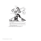
b.
Using the tool, carefully place the microprocessor into the socket.
c. Squeeze the bladder of the tool to release the microprocessor from the
suction cup.
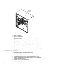
7. Close the microprocessor bracket frame; then, close the microprocessor
retention latch and lock it securely in place.
8. Close the microprocessor-release lever to secure the microprocessor.
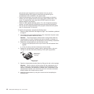
9. Make sure that the heat-sink release lever is open.
10. If necessary, remove the cover from the bottom of the heat sink.
11. Place the tab on the heat sink into the connector in the retention bracket; then,
rotate the heat sink into place and close the heat-sink release lever.
Note: If you are installing an additional microprocessor in microprocessor
socket 2, you must also install a VRM.
12. If necessary, install a VRM in the connector.
Chapter 2. Installing optional devices 41