


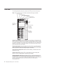
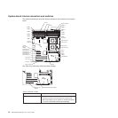
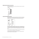
System-board external connectors
The following illustration shows the external input/output connectors and the NMI
switch on the system board.
Mouse
Keyboard
Serial 1
(COM 1)
VGA
LPT
Serial 2
(COM 2)
USB 4
RJ45
RJ45
NMI
USB 3
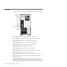
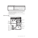
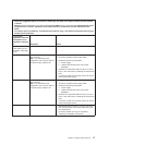
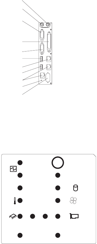
Light path diagnostics panel
The following illustration shows the remind button and the LEDs on the light path
diagnostics panel. The light path diagnostics panel is inside the server under the
left-side cover and the error LEDs are also visible through the left-side cover.
CPU
VRMS_ERR
MEMORY
DASD/
RAID
NMI
SP BUS
FAN
POWER
SUPPLY
PCI
BUS
2
1
CONFIG
TEMP
REMIND
SEE INSIDE COVER FOR MORE SERVICE INFORMATION
Use the remind button on the light path diagnostic panel to acknowledge that an
error has occurred without taking further action. When you push the remind button,
the system error LED will flash every 2 seconds until the error is fixed. If another
error occurs, the system error LED will then stop flashing and return to a solid on
state.
For more information about light path diagnostics, see the Problem Determination
and Service Guide on the IBM System x Documentation CD.
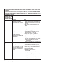
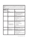
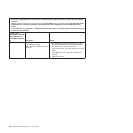
The following table lists the light path diagnostics LEDs, the problems that they
indicate, and actions to solve the problems.
16 IBM System x3500 Type 7977: User’s Guide