


User manual
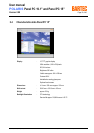
POLARIS Panel PC 19.1'' and Panel PC 15''
Version 2.00 Page 16 of 46
E_BMS790_POLARIS_PanelPC_19+15_Rev1.doc • User manual for POLARIS Panel PC 19.1" and 15" • Revision 1 / Status: January, 3
rd
, 2006 • Technical data subject to change
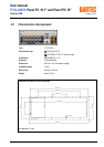
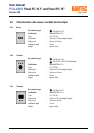
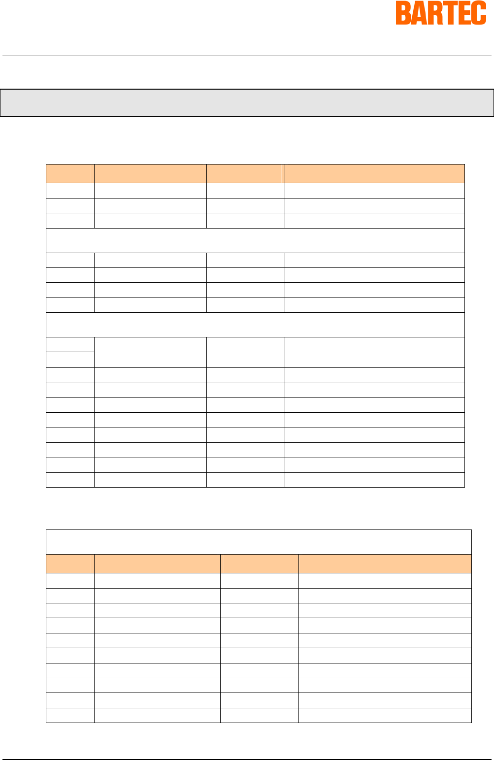
3. Terminal assignment
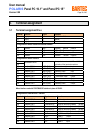
3.1 Terminal assignment Ex e
Terminal Interface Signal Remarks
X10 Supply L AC 230 V ± 10 %
X11 Supply N Neutral
X12 Supply PE Protective earth
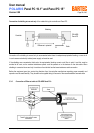
Configuration of RS422 interface of Ethernet 10BaseT
X13 Ethernet RxD + 10BaseT Receive positive
X14 Ethernet RxD - 10BaseT Receive negative
X15 Ethernet TxD + 10BaseT Transmit positive
X16 Ethernet TxD - 10BaseT Transmit negative
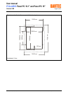
Configuration of RS422 interface
X17 Jumper between terminal X17 and X18 for
X18
Termination On/Off
activation of the terminator resistors
X19 Interface COM 1 TxD B (TxD+) Transmission cable Input
X20 Interface COM 1 TxD A (TxD-) Transmission cable Input
X21 Interface COM 1 RxD B (RxD+) Receiving cable Input
X22 Interface COM 1 RxD A (RxD-) Receiving cable Input
X23 Interface COM 1 TxD B (TxD+) Transmission cable Output
X24 Interface COM 1 TxD A (TxD-) Transmission cable Output
X25 Interface COM 1 RxD B (RxD+) Receiving cable Output
X26 Interface COM 1 RxD A (RxD-) Receiving cable Output
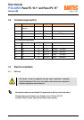
When interface used with PROFIBUS-DP interface in place of RS422:
Configuration of PROFIBUS-DP interface
Terminal Interface Signal Remarks
X17 GND PROFIBUS PE Additional ground
X18 not connected N.C.
X19 Interface COM 1 Termination B2 Bridge for terminating network (B1-B2)
X20 Interface COM 1 Termination A2 Bridge for terminating network (A1-A2)
X21 Interface COM 1 Termination B1 Bridge for terminating network (B1-B2)
X22 Interface COM 1 Termination A1 Bridge for terminating network (A1-A2)
X23 Interface COM 1 Out B Signal B Output
X24 Interface COM 1 Out A Signal A Output
X25 Interface COM 1 In B Signal B Input
X26 Interface COM 1 In A Signal A Input