


User manual
POLARIS Panel PC 19.1'' and Panel PC 15''
Version 2.00 Page 27 of 46
E_BMS790_POLARIS_PanelPC_19+15_Rev1.doc • User manual for POLARIS Panel PC 19.1" and 15" • Revision 1 / Status: January, 3
rd
, 2006 • Technical data subject to change
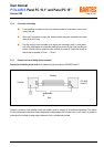
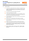
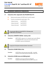
6. Connection cables (pin assignment)
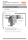
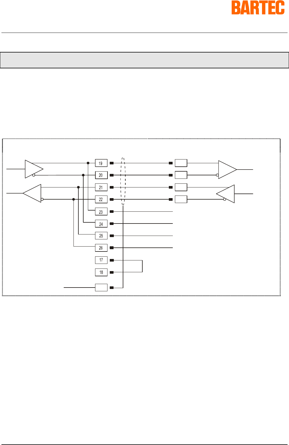
6.1 RS 422 interface
Connection of a controller via an RS 422 interface of the POLARIS Panel PC.
RS422 Modul
Terminal compartment of the POLARIS Panel PC Controller
PE
TxD A (TxD-)
TxD B (TxD+)
RxD A (RxD-)
RxD B (RxD+)
RxD A (RxD-)
RxD B (RxD+)
TxD A (TxD-)
TxD B (TxD+)
Data In
Data In
Data Out
Data Out
Pins 19-23, 20-24, 21-25, 22-26 are already connected inside.
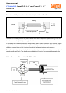
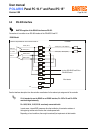
In most cases, internal EMC measures allow the installation of termination resistors at the
beginning and the end of the bus line to be dispensed with.
Depending on local conditions, there might occasionally be impairment of data transfer.
to other POLARIS Panel PC's or
POLARIS Control
if final device