


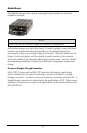

Unmanaged Modules
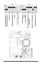
Before installing the iMcV-T1/E1/J1 module into an unmanaged chassis, configure the
module hardware-selectable features via DIP switches located at position S3 and S2
on the PCB (refer to the
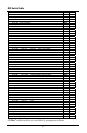
DIP Switch Table
section for more information). The jumpers
located at positions JP1 and JP2 are factory configured— DO NOT CHANGE.
Description of DIP Switch-Selectable Options
The iMcV-T1/E1/J1 module includes movable DIP switches for hard switching the
optional features. Some of these switch options are overridden by the management
setting of a managed chassis (refer to the
DIP Switch Table
section for a list of the
iView
2
managed switches).
This module is shipped in the standard T1 option configuration. The following
section contains a brief description of the available options.
T1/E1/J1 Mode
This option allows you to selects the data rate standard that the module will use when
converting: T1/J1 (default) or E1. The default is OFF, T1/J1 mode selected.
Receive Equalizer Gain Limit (EGL)
This option allows you to compensate for diminishing signal intensity over the data
line by adjusting the sensitivity of the UTP receiver. By setting the Receive Equalizer
Gain Limit, very long copper lines can be utilized.
Line Encoding
This option allows you to set the transmit/receive encoding for HDB3, B8ZS or AMI
(default).
NOTE
There are currently no applications that use any other settings than
AMI encoding
and
NRZ disabled
(Passive mode). Changing the encoding setting to anything
other than
AMI
can result in data corruption.
Transmit LIU Waveshape (Line Build-out)
This option allows you to control the waveshape being output by the transmitter.
This helps to correct problems related to long cables. Improperly setting this switch
will cause signal degradation.
11