


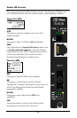

About the iMcV-T1/E1/J1
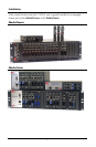
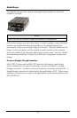
The iMcV-T1/E1/J1™ chassis mounted media conversion module allows you to
extend the distances between T1, J1, and E1 copper telephony systems by adding a
fiber segment. The distances you can add range from 2km to 100km depending on
the module used and the fiber type available.
Contents
This box contains the following items:
•
1 - iMcV-T1/E1/J1 Module
•
1 - Operation Manual
Prerequisites
Before you install the iMcV-T1/E1/J1 modules, perform the following:
•
Make sure you have the correct modules for your fiber type and your distance
requirements.
•
Make sure that T1 UTP lines
DO NOT
use simplex power (no wet lines).
•
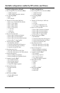
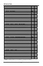
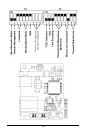
Before you install the iMcV-T1/E1/J1 modules you must verify the DIP switches
are configured for the feature wanted.
•
Make sure you deploy the iMcV-T1/E1/J1 modules in pairs.
•
Make sure the Remote Chassis is not managed.
NOTE
The iMcV-T1/E1/J1 modules are delivered pre-configured for standard T1
operation in Passive mode. To enable remote management you must move DIP
switch S2-2 to the “ON” position on the Remote module (refer to the DIP switch
diagram and table).
4