1 - 13
Modular LYNX System
Modular LYNX System 12.05.2003
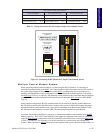
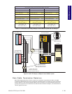
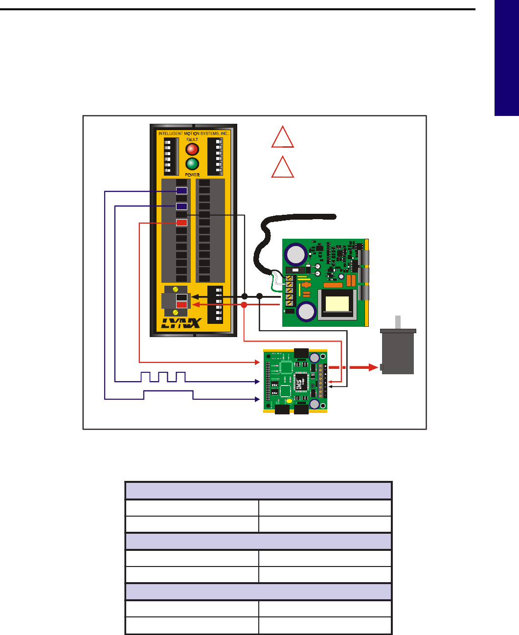
LYNX Control Module with IMS Driver
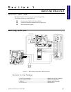
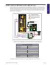
In this example, power is connected to the LYNX Control Module via connector P1. All optional plug-on
modules are then powered from the LYNX Control Module. In this configuration, pins 5 and 6 on connector
P2 of the Control Module become +5VDC (150mA, internally limited) regulated outputs. If an encoder is to
be used in the system, it may be powered via these pins. Below is a table of recommended power supply
specifications for each IMS drive.
*The output current needed is dependant on the supply voltage, motor selection and load.
Figure 4.1: Power Configuration. LYNX Control Module and external IMS Driver
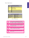
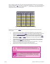
snoitadnemmoceRylppuSrewoP
epyTdednemoceRCDdetalugernU
egatloVelppiR%01±
H384MI/384MIhtiWdesUnehW
egatloVtuptuOCDV54+ot21+
tnerruCtuptuO*)kaeP(A4).pyT(A2
H508MI/508MIhtiWdesUnehW
egatloVtuptuOCDV57+ot42+
tnerruCtuptuO*)kaeP(A6).pyT(A4
ISP200-4
DIR+
DIR-
SCK-
SCK+
GND
+5V
RX-
RX+
TX-
TX+
CGND
RX
TX
22
21
23
24
25
26
31
32
33
34
35
36
IG
123456
123456 123456
22
21
23
24
25
26
31
32
33
34
35
36
GND
V+
A1
A0
A2
PT
HI
UG
TM
Motor Driver
Stepping Motor
ZN429D
GP59627A
ZN429D
GP59627A
AC Line
Power Supply
+5VDC Opto Supply
Step Clock Input
Direction Input
SCLK+
DIR+
+5VDC
OUTPUT
!
!
Ensure that the DC Output of
the Supply Does Not Exceed
the Maximum Driver Input Voltage!
All Power Supply Wiring Should Be
Shielded Twisted Pair to Reduce
Electrical Noise!
+V
GND


