


1 - 21
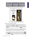
Modular LYNX System
Modular LYNX System 12.05.2003
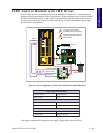
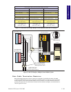
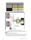
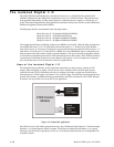
Multiple Controller System
When using the RS-485
interface in a Multiple Control-
ler System, the Host PC as well
as all of the control modules
communicate on the RS-485
interface. In this case, there is
no Host Interface Control
Module, so all control modules
in the system should have
their Host switch OFF or
HOST flag set to False (0).
The Host PC will be equipped
with an RS-485 board or RS-
232 to 485 converter.
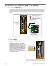
In systems with multiple
controllers it is necessary to
communicate with the control
modules using PARTY Mode
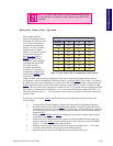
of operation. The LYNX
Control modules in the system are configured for this mode of operation by setting the Party Switch
(configuration switch #3, labeled PT) to the ON position or setting the PARTY Flag to True (1), in software.
It is necessary for all of the controllers in a system to have this configuration selected. When operating in
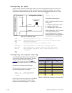
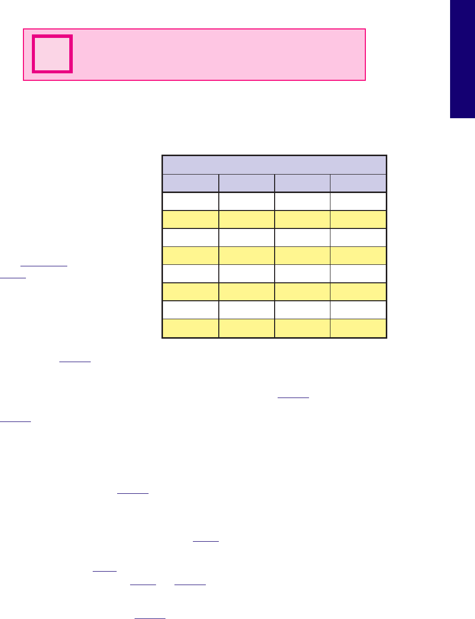
PARTY Mode each control module in the system will need a unique address, or name, to identify it in the
system. This can be done using configuration switches A0-A2, or by using the software command SET DN.
For example, to set the name of a controller to “A” you would use the following command: SET DN = “A”.
The factory default name is “!”. To set the address of the controller using the configuration switches use
the above table.
In setting up your system for PARTY operation the most practical approach would be to observe the
following steps:
1. Connect the Host Control Module to the Host PC configured for Single Mode Operation.
2. Establish communications with the HOST Control Module. Using the Command: SET DN or
the configuration switches, give the controller a unique name. If using the software command
this can be any upper or lower case ASCII character or number 0-9. Save the name using the
command SAVE.
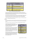
3. Set the appropriate HOST and PARTY configuration in accordance with the following table
and diagram. Remove power.
4. Connect the next control module in the system in accordance with the following table and
diagram, setting the PARTY switch in the ON position. If you desire you can set the PARTY
Flag to “1” in software later and turn the switch off.
5. Establish communications with this module using the factory default name “!”. This name
cannot be reused. Rename and save the new name. Remove power.
6. Repeat the last two steps for each additional control module in the system.
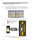
NOTE: The HOST switch MUST be off to communicate with the
Control Module in a Single Controller System using the RS-485
Interface.
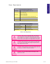
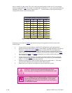
N
sehctiwSnoitarugifnoCsserddAedoMytraP
sserddA 2A 1A 0A
enoN
FFOFFOFFO
A
FFO FFO NO
B
FFONOFFO
C
FFO NO NO
D
NOFFOFFO
E
NO FFO NO
F
NONOFFO
G
NO NO NO
Table 5.5: Party Mode Address Configuration Switch Settings