


1 - 17
Modular LYNX System
Modular LYNX System 12.05.2003
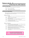
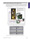
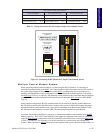
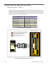
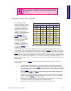
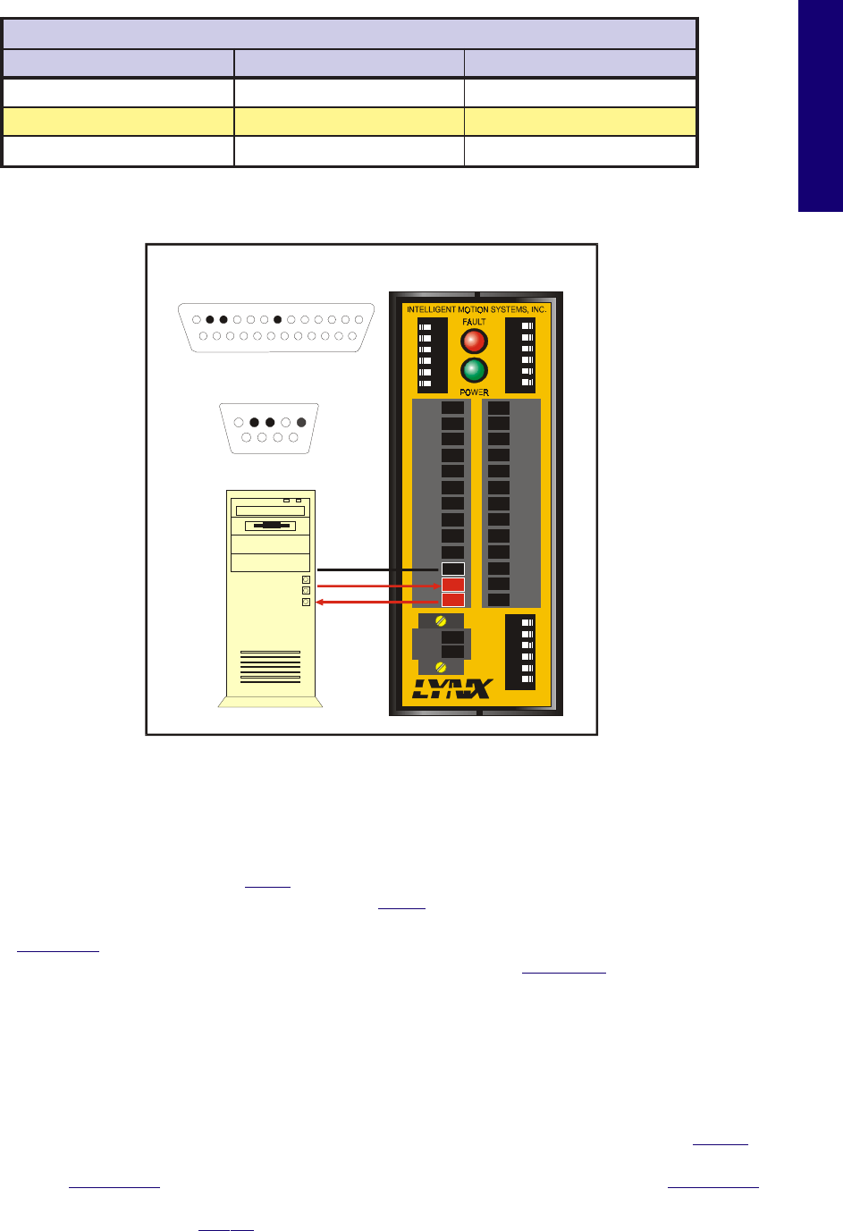
Figure 5.1: Connecting the RS-232 Interface, Single Control Module System
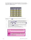
Table 5.1: Wiring Connections: RS-232 Interface Single Control Module System
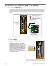
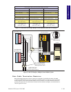
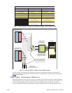
Multiple Control Module System
When connecting multiple control modules in a system using the RS-232 interface, it is necessary to
establish one control module as the HOST. This control module will be connected to the Host PC exactly as
the system using a single control module. The system HOST is established by one of two methods, by
manually selecting the Host switch (configuration switch #2, labeled HI) to the ON position, or by setting
the HOST Flag to True (1) in software. The remaining control modules in the system must then be connected
to the HOST control module using the RS-485 interface and will have their Host switch set to OFF (HOST
Flag = 0).
In this interface configuration, Host PC communications will be received by the Host Control Module via
RS-232 and forwarded to all of the other control modules in the system via the RS-485 channel. Responses
from the individual control modules in the system will be routed back to the Host Control Module via the
RS-485 channel, then internally converted to RS-232 before being forwarded back to the Host PC.
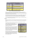
In systems with multiple controllers it is necessary to communicate with the control modules using PARTY
Mode of operation. The LYNX Control Modules in the system are configured for this mode of operation by
setting the Party Switch (configuration switch #3, labeled PT) to the ON position, or setting the PARTY Flag
to True (1), in software. It is necessary for all of the controllers in a system to have this configuration
selected. When operating in PARTY Mode each control module in the system will need a unique address, or
snoitcennoCdnAgniriW:ecafretnI232-SR
eludoMlortnoCXNYL CPnotroPlaireSniP52 CPnotroPlaireSniP9
21niP)XR(ataDevieceR 2niP)XT(ataDtimsnarT 3niP)XT(ataDtimsnarT
31niP)XT(ataDtimsnarT 3niP)XR(ataDevieceR 2niP)XR(ataDevieceR
11niPdnuorGsnoitacinummoC 7niPdnuorGsnoitacinummoC 5niPdnuorGsnoitacinummoC
DIR+
DIR-
SCK-
SCK+
GND
+5V
RX-
RX+
TX-
TX+
CGND
RX
TX
22
21
23
24
25
26
31
32
33
34
35
36
IG
123456
123456 123456
22
21
23
24
25
26
31
32
33
34
35
36
GND
V+
A1
A0
A2
PT
HI
UG
TM
CGND
RX
TX
Host PC
1 2 3 4 5 6 7 8 9 10 11 12 13
14 15 16 17 18 19 20 21 22 23 24 25
25 PIN Serial Port
on Host PC
9 PIN Serial Port
on Host PC
1 2 3 4 5
6 7 8 9