


1 - 3
Modular LYNX System
Modular LYNX System 12.05.2003
Typical Functions of the Differential I/O.................................................................................................................................... 1-34
Connecting and Using an Encoder ................................................................................................................................ 1-34
Translating the EUNIT Variable to a Dimension of Distance...................................................................................... 1-35
Half Axis Operation (Follower) .................................................................................................................................... 1-36
One and a Half Axis Operation (RATIOE)................................................................................................................... 1-37
Section 7: The LYNX Control Module (LX-CM100-000) .................................................................................................. 1-39
Section Overview ......................................................................................................................................................................... 1-39
Hardware Specifications ............................................................................................................................................................... 1-39
Environmental Specifications....................................................................................................................................... 1-39
Mechanical Specification .............................................................................................................................................. 1-39
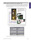
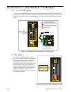
Connection Overview .................................................................................................................................................................. 1-40
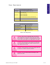
Power Requirements ...................................................................................................................................................... 1-40
LED Indicators ............................................................................................................................................................................. 1-41
Pin Assignment and Description.................................................................................................................................................. 1-41
Switch Assignments ...................................................................................................................................................................... 1-42
Section 8: The LYNX Control Module (Combination) .................................................................................................... 1-43
Section Overview ......................................................................................................................................................................... 1-43
Hardware Specifications ............................................................................................................................................................... 1-43
Environmental Specifications....................................................................................................................................... 1-43
Mechanical Specification .............................................................................................................................................. 1-43
Connection Overview .................................................................................................................................................................. 1-44
Power Requirements ...................................................................................................................................................... 1-44
LED Indicators ............................................................................................................................................................................. 1-45
Pin Assignment and Description.................................................................................................................................................. 1-45
Switch Assignments ...................................................................................................................................................................... 1-46
Section 9: The Isolated Digital I/O Module ...................................................................................................................... 1-47
Section Overview ......................................................................................................................................................................... 1-47
Hardware Specifications ............................................................................................................................................................... 1-47
Environmental Specification ........................................................................................................................................ 1-47
Mechanical Specification .............................................................................................................................................. 1-47
Connection Overview .................................................................................................................................................................. 1-48
Pin Assignments And Description ............................................................................................................................................... 1-48
Switch Assignments And Description .......................................................................................................................................... 1-49
Input Specifications...................................................................................................................................................................... 1-49
Input Filtering .............................................................................................................................................................................. 1-50
Output Specifications ................................................................................................................................................................... 1-50
Section 10: The Differential Digital I/O Module.............................................................................................................. 1-51
Section Overview ......................................................................................................................................................................... 1-51
Hardware Specifications ............................................................................................................................................................... 1-51
Environmental Specification ........................................................................................................................................ 1-51
Mechanical Specification .............................................................................................................................................. 1-51
Connection Overview .................................................................................................................................................................. 1-52
Power Requirements ..................................................................................................................................................................... 1-52
Pin Assingments And Description ............................................................................................................................................... 1-53
Input Specifications...................................................................................................................................................................... 1-53
Input Filtering .............................................................................................................................................................................. 1-54
Output Specifications ................................................................................................................................................................... 1-55
List of Tables
Table 4.1: Power Requirements ............................................................................................................................................... 1-15
Table 5.1: Wiring Connections: RS-232 Interface Single Control Module System................................................................. 1-17
Table 5.2: Party Mode Address Configuration Switch Settings ............................................................................................... 1-18
Table 5.3: Connections and Settings Multiple Control Module System, RS-232 Interface .................................................... 1-19
Table 5.4: RS-485 Interface Connections ............................................................................................................................... 1-20
Table 5.5: Party Mode Address Configuration Switch Settings ............................................................................................... 1-21
Table 5.6: RS-485 Interface Connections and Settings, Multiple Control Module System .................................................... 1-22
Table 5.7: ASCII Mode Special Command Characters............................................................................................................. 1-24
Table 5.8: Binary Hex Codes ................................................................................................................................................... 1-24
Table 6.1: System I/O Availability by Module ......................................................................................................................... 1-25
Table 6.2: IOS Variable Settings ............................................................................................................................................... 1-27
Table 6.3: Digital Filter Settings for the Isolated I/O .............................................................................................................. 1-28
Table 6.4: Binary State of Outputs .......................................................................................................................................... 1-30
Table 6.5: The Four Clocks and Their Default Line Placement ............................................................................................. 1-31
Table 6.6: Digital Filter Settings for the Differential I/O........................................................................................................ 1-33