


1 - 14 Modular LYNX System 12.05.2003
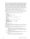
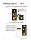
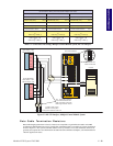
Stand-alone or with Optional I/O Modules
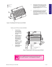
+12 to +75VDC Supply
A +12 to +75VDC unregulated supply connected to P1 provides power to the LYNX Control Module and
any optional I/O modules. As in the LYNX Controller with Driver (s) Configuration, pins 5 (Ground) and 6
(+5VDC) on connector P2 of the Control Module becomes a +5VDC (150mA, internally limited) regulated
output.
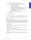
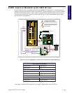
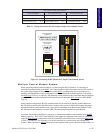
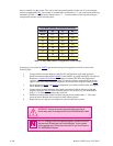
+5 VDC Supply
A +5VDC ±5% regulated supply connected to
pins 5 (Ground) and 6 (+5VDC) on connector P2
provides power to the LYNX Control Module
and any optional I/O modules. Figure 4.3. It is
assumed that external drives are being used and
power is supplied to these drives separately.
The LYNX Controller internally limits the current
to 800mA. While the LYNX Controller and I/O
Modules will only require 368mA, a fully
configured LYNX System utilizing the outputs
may require up to 800mA.
Figure 4.3: Stand-alone Power Configuration: 5 VDC
DIR+
DIR-
SCK-
SCK+
GND
+5V
RX-
RX+
TX-
TX+
CGND
RX
TX
22
21
23
24
25
26
31
32
33
34
35
36
IG
123456
123456 123456
22
21
23
24
25
26
31
32
33
34
35
36
GND
V+
A1
A0
A2
PT
HI
UG
TM
+5VDC ±5%
Regulated Supply
(Up to 800mA)
Figure 4.2: Stand-alone Power Configuration: 12 - 75 VDC Supply
ISP200-4
DIR+
DIR-
SCK-
SCK+
GND
+5V
RX-
RX+
TX-
TX+
CGND
RX
TX
22
21
23
24
25
26
31
32
33
34
35
36
IG
123456
123456 123456
22
21
23
24
25
26
31
32
33
34
35
36
GND
V+
A1
A0
A2
PT
HI
UG
TM
AC Line
+12 to +75VDC
Power Supply
(IMS ISP 200-4 Shown)
+5VDC, 150mA
Internally Limited
Output
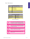
!
!
Ensure that the DC Output of
the Supply Does Not Exceed
the Maximum Driver Input Voltage!
All Power Supply Wiring Should Be
Shielded Twisted Pair to Reduce
Electrical Noise!