POINTER
TO
INTERRUPT
HANDLER
FOR:
INTERRUPT
255
INTERRUPT
254
INTERRUPT
253
INTERRUPT
1
INTERRUPT
0
POINTER
POINTER
POINTER
~
POINTER
POINTER
REAL ADDRESS MODE
..
~~
PHYSICAL
ADDRESS
1020
1016
1012
4
0
1
0
•
19
I
. . . .
. .
01
VECTOR
101
oj
10
9 2 1 0
G3010a
Figure 5-3.
Interrupt
Vector
Table
for
Real Address Mode
Table 5-1.
Interrupt
Processing Order
Order
Interrupt
1.
Instruction exception
2.
Single step
3.
NMI
4.
Processor extension segment overrun
5.
INTR
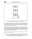
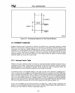
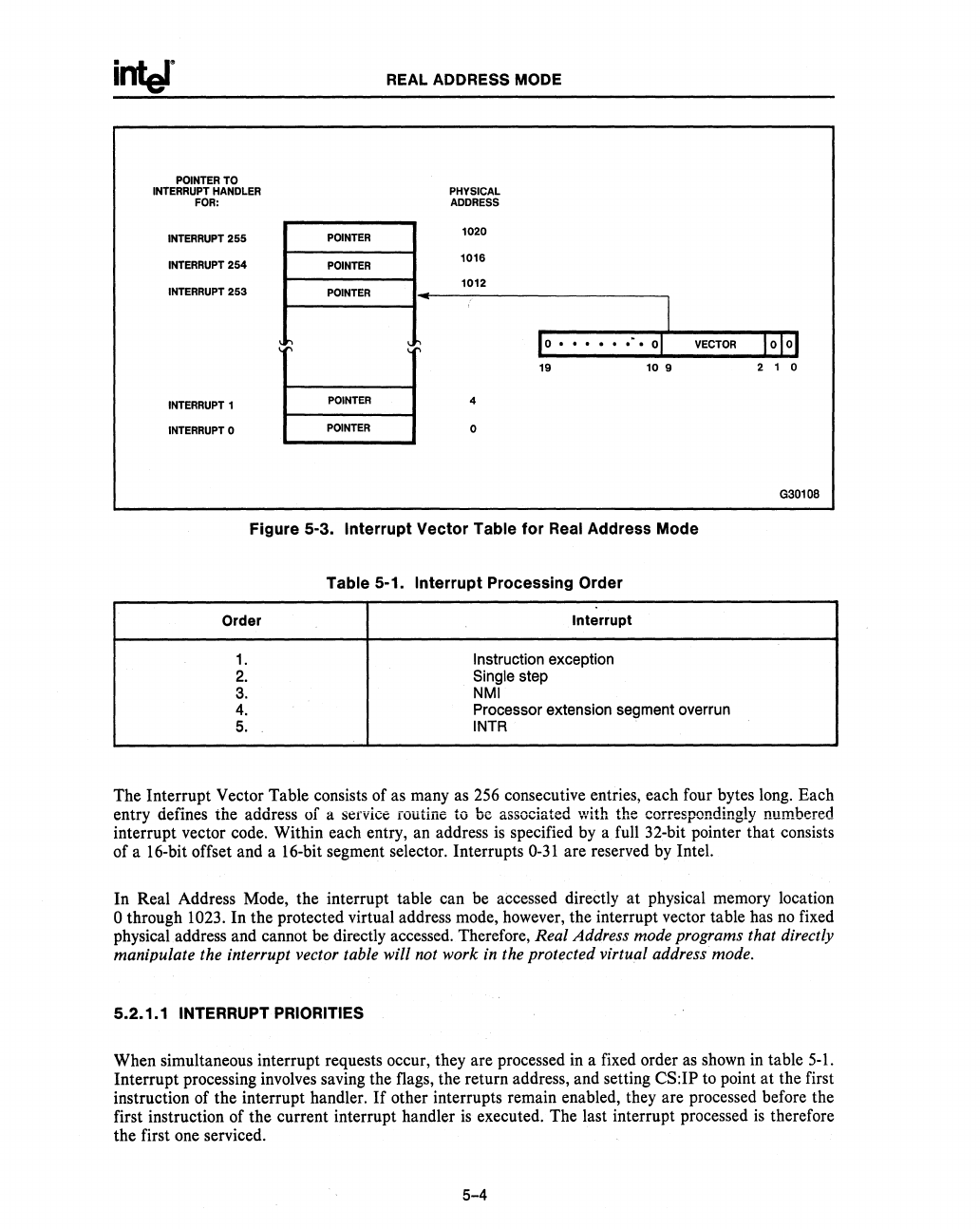
The Interrupt Vector Table consists of as many as 256 consecutive entries, each four bytes long. Each
entry defines the address of a service routine to
be associated \vith the correspondingly numbered
interrupt vector code. Within each entry, an address
is
specified by a full 32-bit pointer that consists
of a 16-bit offset and a 16-bit segment selector. Interrupts
0-31
are reserved by Intel.
In Real Address Mode, the interrupt table can be accessed directly
at
physical memory location
o through 1023. In the protected virtual address mode, however, the interrupt vector table has
no
fixed
physical address and cannot be directly accessed. Therefore,
Real Address mode programs that directly
manipulate the interrupt vector table will not work
in
the protected virtual address mode.
5.2.1.1 INTERRUPT PRIORITIES
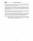
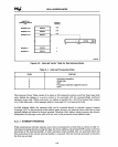
When simultaneous interrupt requests occur, they are processed
in
a fixed order
as
shown
in
table
5-1.
Interrupt processing involves saving the flags, the return address, and setting CS:IP to point at the first
instruction of the interrupt handler.
If
other interrupts remain enabled, they are processed before the
first instruction of the current interrupt handler
is
executed. The last interrupt processed
is
therefore
the first one serviced.
5-4


