CHAPTER
10
SYSTEM CONTROL
AND
INITIALIZATION
Special flags, registers, and instructions provide contol of the
~ritical
processes and interaction
in
80286
operations. The flag register includes 3 bits that represent the current
I/O
privilege level (IOPL: 2
bits) and the nested task bit (NT). Four additional registers support the virtual addressing and memory
protection features,
one
points
to
the current Task State Segment and the other three point
to
the
memory-based descriptor tables: GDT, LDT, and IDT. These flags and registers are discussed
in
the
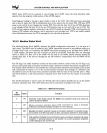
next section. The machine status word, (which indicates processor configuration and status) and the
instructions that load and store it aredisc.u.ssed
in
section 10.2.2.
Similar instructions pertaining
to
the other registers are the subject of sections 10.2 and
10.3.
A detailed
description of initialization states and processes, which appears in section
lOA,
is
supplemented
by
the
extensive example
in
Appendix A. Instructions that validate descriptors and pointers are covered in
section 11.3.
10.1
SYSTEM
FLAGS
AND
REGISTERS
The
10PL
flag (bits
12
and 13 of the flags word) controls access
to
I/O
operations and interrupt
control instructions. These
two
bits represent the maximum privilege level (highest numerical CPL)
at
which the task
is
permitted
to
perform
I/O
instructions. Alteration of the
10PL
flags
is
restricted to
programs
at
level 0 or
to
a task switch.
IRET uses the
NT
flag
to
select the proper return; if
NT
=
0,
the normal return within a task
is
performed.
As
discussed
in
Chapter
8,
the nested task flag (bit
14
of flags)
is
set when a task initiates
a task switch via a CALL
or'INT
instruction. The old and
new
task state segments are marked busy
and the backlink field of the
new
TSS
is
set
to
the old TSS selector. An interrupt that
does
not cause
a task switch
will
clear
NT
after the old
NT
state
is
saved.
To
prevent a program from causing an
illegal task switch by setting
NT
and then executing IRET, a zero selector should be placed
in
the
backlink field of the
TSS. An illegal task switch using IRET
will
then cause exception
13.
The instruc-
tions
POPF and IRET can also set or clear
NT
when flags are restored from the stack. POPF and
IRET can also change the interrupt enable flag.
If
CPL
~
IOPL, then the Interrupt Flag (IF) can be
changed
by
POPF and IRET. Otherwise, the state of the IF bit in the
new
flag
~ord
is
ignored by
these instructions. Note that the CLI and
STI instructions are valid only when CPL
::s
10PL; other-
wise
exception
13
occurs.
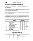
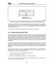
10.1.1 Descriptor Table Registers.·
The three descriptor tables used for all memoryaccesseSfue based
at
addresses supplied
by
(stored in)
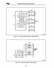
three registers: the global descriptor table register (GDTR), the interrupt descriptor table register
(IDTR), and the local descriptor table register (LDTR). Each register contains a 24-bit base field and
a 16-bit limit field. The base field gives the real memory address of the beginning of the table; the
limit field tells the maximum offset permitted in accessing table entries.
See figures
10-1
thru
10-3.
The LDTR also contains a selector field that identifies the descriptor for that table. LDT descriptors
must reside
in
the GDT.
10-1


