OVERVIEW OF NUMERIC PROCESSING
80287
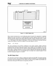
STACK:
TAG FIELD
79
78
64
63
0
1
0
Rl
SIGN
EXPONENT SIGNIFICAND
R2
R3
R4
r--
-
R5
R6
R7
R8
15 0
CONTROL REGISTER
STATUS REGISTER
TAG
WORD
t-
INSTRUCTION POINTER
DATA
POINTER
G3010B
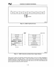
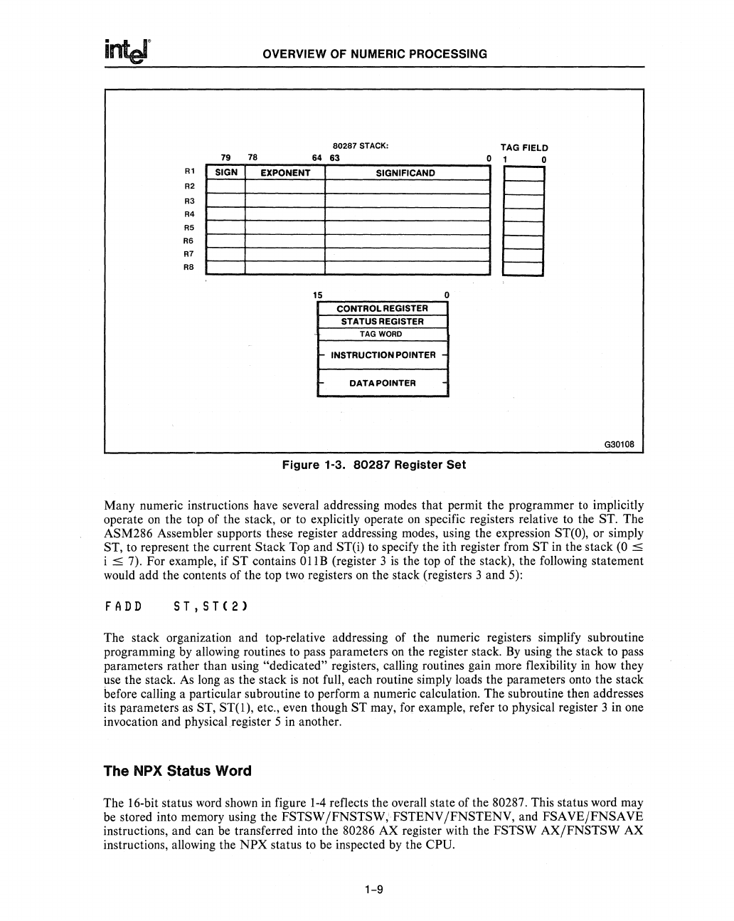
Figure
1-3_
80287
Register
Set
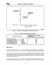
Many numeric instructions have several addressing modes that permit the programmer
to
implicitly
operate
on
the top of the stack, or
to
explicitly operate
on
specific registers relative
to
the ST. The
ASM286 Assembler supports these register addressing modes, using the expression
ST(O),
or simply
ST, to represent the current Stack Top and STeil
to
specify the ith register from
ST
in the stack
(0
::s
i
::s
7). For example, if
ST
contains
OllB
(register 3
is
the top of the stack), the
following
statement
would add the contents of the top
two
registers
on
the stack (registers 3 and
5):
FADD
ST,ST(2)
The stack organization and top-relative addressing of the numeric registers simplify subroutine
programming by allowing routines
to
pass parameters
on
the register stack.
By
using the stack to pass
parameters rather than using
"dedicated" registers, calling routines gain more flexibility
in
how
they
use the stack.
As
long
as
the stack
is
not full, each routine simply loads the parameters onto the stack
before calling a particular subroutine
to
perform a numeric calculation. The subroutine then addresses
its parameters
as
ST,
ST(l),
etc., even though
ST
may, for example, refer
to
physical register 3 in one
invocation and physical register 5
in
another.
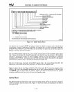
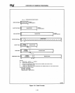
The NPX Status Word
The l6-bit status word shown in figure
1-4
reflects the overall state of the 80287. This status word may
be
stored into memory using the FSTSW/FNSTSW,'FSTENV/FNSTENV, and FSAVEjFNSAVE
instructions, and can
be
transferred into the 80286 AX register with the FSTSW
AX/FNSTSW
AX
instructions, allowing the
NPX
status
to
be
inspected
by
the CPU.
1-9


