8086
lines D
7
–D
0
as supplied by the inerrupt system logic
(ie 8259A Priority Interrupt Controller) This byte
identifies the source (type) of the interrupt It is multi-
plied by four and used as a pointer into an interrupt
vector lookup table as described earlier
BUS TIMINGMEDIUM SIZE SYSTEMS
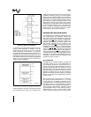
For medium size systems the MNMX
pin is con-
nected to V
SS
and the 8288 Bus Controller is added
to the system as well as a latch for latching the sys-
tem address and a transceiver to allow for bus load-
ing greater than the 8086 is capable of handling
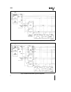
Signals ALE DEN and DTR are generated by the
8288 instead of the processor in this configuration
although their timing remains relatively the same
The 8086 status outputs (S
2
S
1
and S
0
) provide
type-of-cycle information and become 8288 inputs
This bus cycle information specifies read (code
data or IO) write (data or IO) interrupt
acknowledge or software halt The 8288 thus issues
control signals specifying memory read or write IO
read or write or interrupt acknowledge The 8288
provides two types of write strobes normal and ad-
vanced to be applied as required The normal write
strobes have data valid at the leading edge of write
The advanced write strobes have the same timing
as read strobes and hence data isn’t valid at the
leading edge of write The transceiver receives the
usual DIR and G
inputs from the 8288’s DTR and
DEN
The pointer into the interrupt vector table which is
passed during the second INTA cycle can derive
from an 8259A located on either the local bus or the
system bus If the master 8259A Priority Interrupt
Controller is positioned on the local bus a TTL gate
is required to disable the transceiver when reading
from the master 8259A during the interrupt acknowl-
edge sequence and software ‘‘poll’’
13


