


Intel Desktop Board DX79TO Product Guide
48
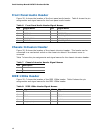
Front Panel Audio Header
Figure 20, A shows the location of the front panel audio header. Table 6 shows the pin
assignments and signal names for the front panel audio header.
Table 6. Front Panel Audio Header Signal Names
Pin Signal Name Pin Signal Name
1 PORT 1L 2 GND
3 PORT 1R 4 PRESENCE#
5 PORT 2R 6 SENSE1_RETURN
7 SENSE_SEND 8 KEY (no pin)
9 PORT 2L 10 SENSE2_RETURN
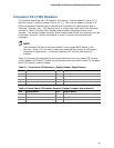
Chassis Intrusion Header
Figure 20, B shows the location of the chassis intrusion header. This header can be
connected to a mechanical switch on the chassis to detect if the chassis cover is
removed.
Table 7 shows the pin assignments and
signal names for the chassis intrusion header.
Table 7. Chassis Intrusion Header Signal Names
Pin Description
1 Intruder
2 Ground
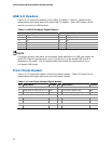
IEEE 1394a Header
Figure 20, C shows the location of the IEEE 1394a header. Table 8 shows the pin
assignments and signal names for the IEEE 1394a header.
Table 8. IEEE 1394a Header Signal Names
Pin Signal Name Pin Signal Name
1 TPA1+ 2 TPA1-
3 Ground 4 Ground
5 TPA2+ 6 TPA2-
7 +12 V 8 +12 V
9 Key (no pin) 10 Ground