


Installing and Replacing Desktop Board Components
51
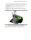
Alternate Front Panel Power LED Header
Figure 20, H shows the location of the alternate front panel power LED header. Pins 1
and 3 of this header duplicate the signals on pins 2 and 4 of the front panel header. If
your chassis has a three-pin power LED cable, connect it to this header.
Table 13 shows the pin assignments and
signal names for the alternate front panel
power LED header.
Table 13. Alternate Front Panel Power LED Header Signal Names
Pin Description In/Out
1 Front panel green LED Out
2 No pin
3 Front panel yellow LED Out
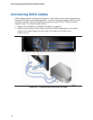
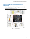
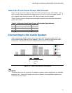
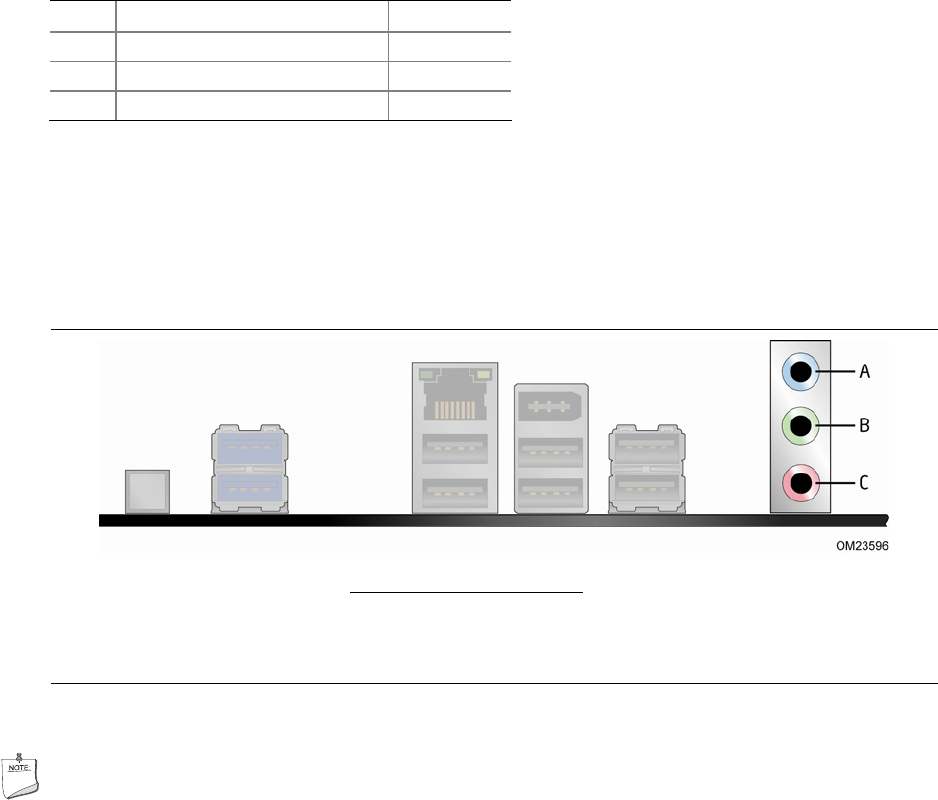
Connecting to the Audio System
After installing the RealTek audio driver from the Intel
®
Express Installer DVD, the
multi-channel audio feature can be enabled. Figure 21 shows the back panel audio
connectors
. The default connector assignments are shown in the table.
Item Description
A Line In
B Line Out
C Mic In
Figure 21. Back Panel Audio Connectors
NOTE
The back panel line out connector is designed to power either headphones or amplified
speakers only. Poor audio quality may occur if passive (non-amplified) speakers are
connected to this output.