


Desktop Board Features
13
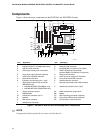
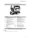
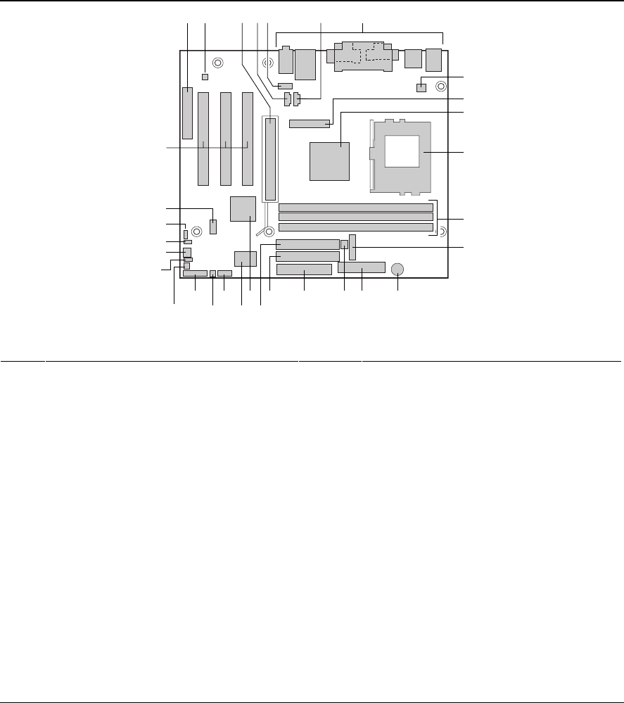
Figure 2 shows the major components on the D815EFV and D815EPFV boards.
OM11630
G
FC D
K
I
J
H
T
S
RX V
W U
Q NO
BA
EE
Z
DD
CC
E
L
M
AA
BB
Y
P
Item Description Item Description
A CNR connector (optional) Q Diskette drive connector
B Analog Devices Inc. AD1885 audio codec R Primary IDE connector
C AGP universal connector S Secondary IDE connector
D ATAPI-style auxiliary line in connector T Intel 82801BA I/O Controller Hub (ICH2)
E Front panel audio connector (optional) U SMSC LPC47M132 I/O controller
(optional SMSC LPC47M142 I/O controller)
F ATAPI-style CD-ROM connector V Serial port B connector
G Back panel connectors W SCSI hard drive activity LED connector
H Processor fan connector (fan 1, tach) X Front panel switch/LED connector
I Digital Video Output (DVO) connector
(D815EFV only)
Y Alternate front panel power LED connector
J
• Intel 82815E GMCH (D815EFV only)
• Intel 82815EP MCH (D815EPFV only)
Z Chassis intrusion connector
K 370-pin processor socket AA Chassis fan connector (fan 2, tach)
L DIMM sockets BB BIOS configuration jumper block
M Battery CC WOL technology connector (optional)
N Speaker DD Front panel USB connector (optional)
O Main power connector EE PCI bus add-in card connectors
P Chassis fan connector (fan 3)
Figure 2. D815EFV and D815EPFV Desktop Board Components
✏
NOTE
Components labeled optional do not come on all the boards.