


Installing and Replacing Desktop Board Components
29
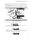
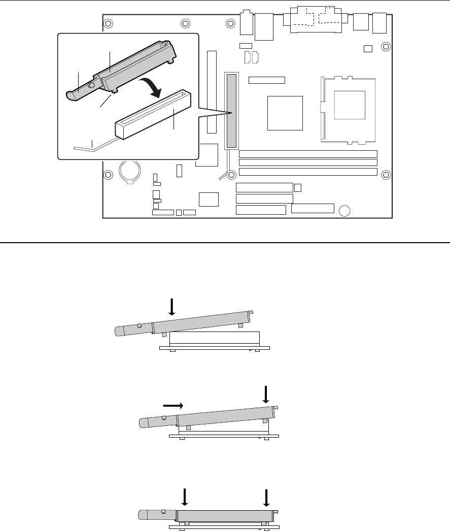
Observe the precautions in “Before You Begin” on page 25. Place the desktop board on top of an
ESD safe surface, component-side up. Follow the steps outlined below to attach the RM (A) to the
AGP universal connector (B):
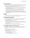
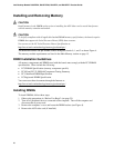
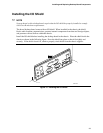
1. Locate the AGP connector (J6C1) on the desktop board as shown in Figure 6. Note that the
desktop board’s silkscreen (C) indicates the correct final position of the lever (E) on the RM.
OM11624
C
B
A
D
E
Figure 6. AGP Connector Location and Retention Mechanism (RM) Placement (Inset)
(the D815EEA2 Board Is Shown)
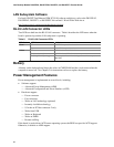
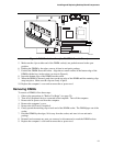
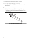
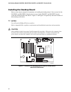
2. Position the RM over the AGP universal connector as shown below.
OM10111
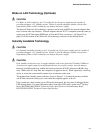
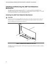
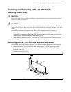
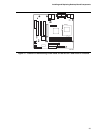
3. Push the lever end of the RM in the direction of the arrow until the two rearmost tabs (D)
spread over the end of the AGP universal connector.
OM10180
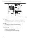
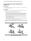
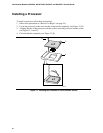
4. Push the free end of the RM over the other end of the AGP connector and press down evenly
on both ends of the RM until all four tabs click underneath the AGP universal connector. Do
not apply unnecessary pressure to avoid damaging the board.
OM10181