


INSTALLATIONS
AFW-3000 User’s Manual 9
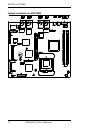
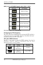
ATX Power Installation
The system power is provided to the AFW-3000 Server Motherboard
with the CN7 and CN8 ATX power connectors. CN8 is a 4-pin power
connector. CN7 is a 20-pin ATX power connector.
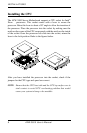
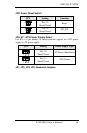
Installing the Memory
The AFW-3000 Server Motherboard supports two DDR memory sockets
for a maximum total memory of 4GB in DDR memory type.
Note: DIMM modules must be DDR/ECC/Reg Only.
Modules “in pairs” must be the same type and size.
The memory module capacities supported are 64MB, 128MB, 256MB,
512MB, 1GB and 2GB. The following table lists the supported DDR
DIMM configurations.
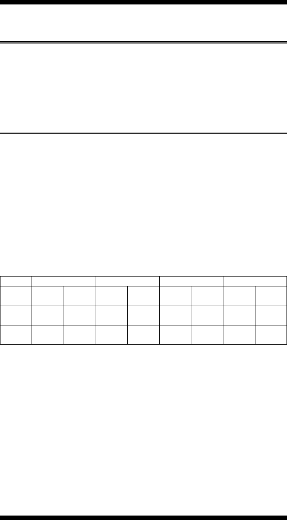
Supported DDR DIMM Configurations.
Density 64 Mbit 128Mbit 256Mbit 512Mbit
Device
Width
X4 X8 X4 X8 X4 X8 X4 X8
Single/
Double
SS/DS SS/DS SS/DS SS/DS SS/DS SS/DS SS/DS SS/DS
184-pin
DDR
128/256MB
64/128MB 256/512MB
128/256MB
512MB
/1GB
256/512MB
1GB/2GB 512MB
/1GB
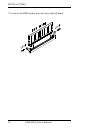
Installing and Removing Memory Modules
To install the DDR modules, locate the memory slot on the Server
Motherboard and perform the following steps:
1. Hold the DDR module so that the keys of the DDR module align with
those on the memory slot.
2. Gently push the DDR module in an upright position until the clips of
the slot close to hold the DDR module in place when the DDR module
touches the bottom of the slot.