


INSTALLATIONS
18 AFW-3000 User’s Manual
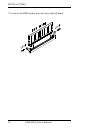
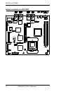
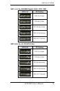
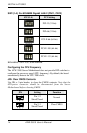
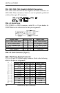
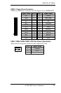
CN1, CN2, CN3, CN4: Gigabit LAN RJ45 Connectors
CN1, CN2, CN3 and CN4 are the Gigabit LAN RJ45 connectors on
AFW-3000. These connectors, however, can be optionally positioned
with four fiber optic SC connectors.
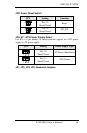
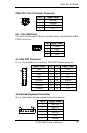
CN5, J9: Serial Ports
CN5 (COM1) is a DB-9 connector, while J9 is a 10-pin header for
COM2. Refer to the table below for their pin assignments.
COM1 COM2
Signal Name Pin # Pin # Signal Name
DCD, Data carrier detect 1 6 DSR, Data set ready
RXD, Receive data 2 7 RTS, Request to send
TXD, Transmit data 3 8 CTS, Clear to send
DTR, Data terminal ready
4 9 RI, Ring indicator
GND, ground 5 10 Not Used
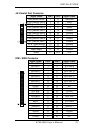
CN6: CF Card Connector (Type 1)
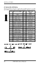
CN7: ATX Power Supply Connector
CN7 is a 20-pin ATX power supply connector. Refer to the following
table for the pin out assignments.
Signal Name Pin # Pin # Signal Name
3.3V 11 1 3.3V
-12V 12 2 3.3V
Ground 13 3 Ground
PS-ON 14 4 +5V
Ground 15 5 Ground
Ground 16 6 +5V
Ground 17 7 Ground
-5V 18 8 Power good
+5V 19 9 5VSB
11 1
20 10
+5V 20 10 +12V