


ESM-2740/2743
42 ESM-2740/2743 User’s Manual
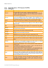
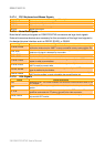
2.4.9.3 Miscellaneous Signals
Signal Signal Description
SPEAKER
PC speaker output signal. This logic-level signal can be connected to an external
transistor in order to drive a piezoelectric or dynamic speaker.
BATT
3V backup cell input. BATT is typically connected to a 3V lithium backup cell for
RTC operation and CMOS register non-volatility in the absence of system power.
I
2
CLK, I
2
DAT
These clock and data lines implement an I
2
C-bus which supports external slave
devices only. Data rate is approximate 1-10kHz. This interface is intended for
support of EEPROMs and other simple I/O-devices.
SMBDATA, SMBCLK
System Management Bus clock and data lines. May be used to support external
SMBUS devices such as temperature and battery monitoring chips. The addresses
of external SMBUS devices must be chosen so they do not conflict with addresses
used internally on the ETX module.
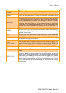
KBINH Keyboard Inhibit. Asserting this pin disables data input from the keyboard.
OVCR#
Over-current detect input. Used to monitor the USB power over-current. Pull with
open collector to GND if over-current is detected.
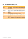
2.4.9.4 Power Control Signals
Signal Signal Description
5V_SB
Power input for the internal suspends and power control circuitry. Connect to a 5V,
100mA stand-by power source available. May be a no-connect if a standby supply
is not available.
PS_ON
Active-low output from ESM-2740/2743. Can be connected to the PS_ON input of
an ATX power supply in order to switch the main output. In order for this pin to
function, 5V_SB must be supplied to the ESM-2740/2743.
PWRBTN#
Power Button Input. Connect to GND with momentary-contact switch or open
collector driver to implement ATX power button control of PS_ON. In order for this
pin to function, 5V_SB must be supplied to the ESM-2740/2743.
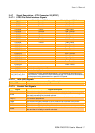
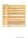
2.4.9.5 Power Management Signals
Signal Signal Description
RSMRST#
Resume Reset input. This input may be driven low by external circuitry in order to
reset the power management logic on the ETX module.
EXTSMI
System management interrupt input. May be driven low by external circuitry to
initiate an SMI.
GPE2#
General purpose power management event input 2. May be driven low by external
circuitry to signal an external power management event. Within the ETX module,
this pin is commonly connected to the chipset’s RING# input.