


28
2
Hardware Installation
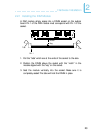
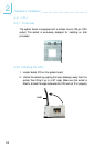
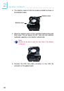
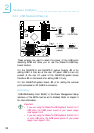
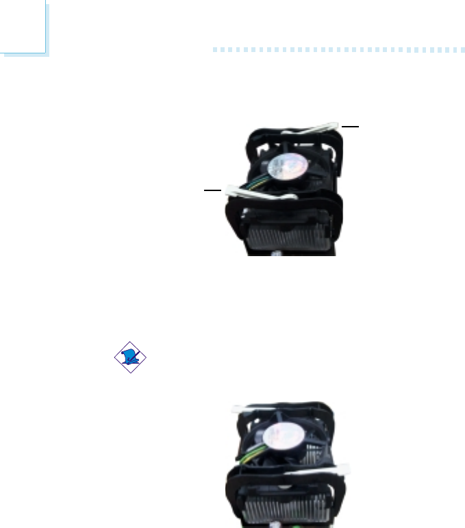
3. The retention levers at this time remains unlocked as shown in
the illustration below.
Retention lever
Retention lever
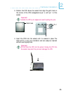
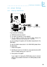
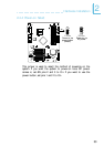
4. Move the retention levers to their opposite directions then push
them down. This will secure the fan / heat sink and retention
mechanism assembly to the retention module base.
Note:
You will not be able to push the lever down if the direction
is incorrect.
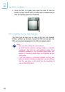
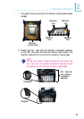
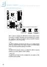
5. Connect the CPU fan’s cable connector to the CPU fan
connector on the system board.