Intel NetStructure
®
MPCBL0010 Single Board Computer
October 2006 Technical Product Specification
Order Number: 304120 141
Hardware Management Overview—MPCBL0010 SBC
10.12.1 Warm Reset
A warm reset occurs when the processor boots after a soft reset request. To qualify as
a warm boot, the reset counter located at 40h:D0h must be non-zero (by default, the
reset counter and reset flag are initialized to 10 and 1234h by the BIOS after a cold
boot). Execution starts at the reset vector. The BIOS initializes and configures all
devices except for memory. Memory contents remain intact except for the first 8 MB.
The BIOS uses the first 8 MB during POST, but does not modify the reset flag or the
reset counter. MCH is not reset, allowing DRAM refresh to continue during the warm
boot.
On every warm boot, the BIOS automatically decrements the reset counter by one.
When the reset counter reaches zero and the soft reset is initiated, a cold boot occurs
instead of a warm boot
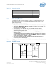
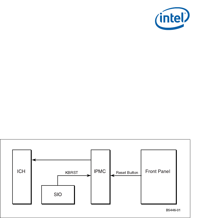
The front panel reset button is connected to IPMC. If the button is pushed, the IPMC
outputs an active signal to the ICH’s RCIN to perform CPU init as the warm reset.
Note: The KBRST (keyboard reset) can be used to cause a warm reset and will be detected by
the IPMC.
10.12.2 Hard Reset
Any reset that does not meet the configuration described in Section 10.12.1, “Warm
Reset” is classified as a cold boot. Execution starts at the reset vector, and the BIOS
initializes and configures all devices, including memory subsystem, as if a hard reset
had occurred. During a cold boot the BIOS initializes the warm reset counter to 10h and
clears the reset flag to 1234h. Software can then read the Reset flag to determine the
type of reset.
10.13 Field Replaceable Unit (FRU) Information
The FRU information provides inventory data about the boards where the FRU
Information Device is located. The part number or version number can be read through
software.
Figure 25. Warm Reset Block Diagram


