


IQ80960RM/RN
Evaluation Board Manual 3-9
Hardware Reference
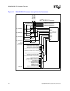
Table 3-11 lists the connectors and LEDs.
Table 3-11. IQ80960RM/RN Connectors and LEDs
Item Description
J1-J4 Secondary PCI bus expansion connector
J5 168-pin SDRAM DIMM socket
J6 JTAG connector
J7 Serial port connector
J8 Logic analyzer connector for flash ROM bus
J10 Logic analyzer connector for Secondary PCI bus arbitration signals
J9, J11, J12 Logic analyzer connector for access to SDRAM bus
J13 Active heatsink connector for example fan monitor circuit
CR1, CR2 Eight user LEDs
CR3 Self-test fail LED
CR4 Battery backup SDRAM, 3.3 V available
CR5 Indicates host system providing 3.3 V to Secondary PCI bus connectors
S1 DIP switch (Table 3-9)