


14
•
Installation
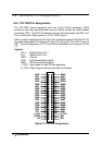
2.6 Connector Pin Assignments
2.6.1 PCI-7200 Pin Assignments
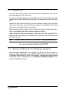
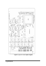
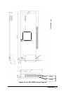
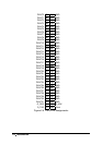
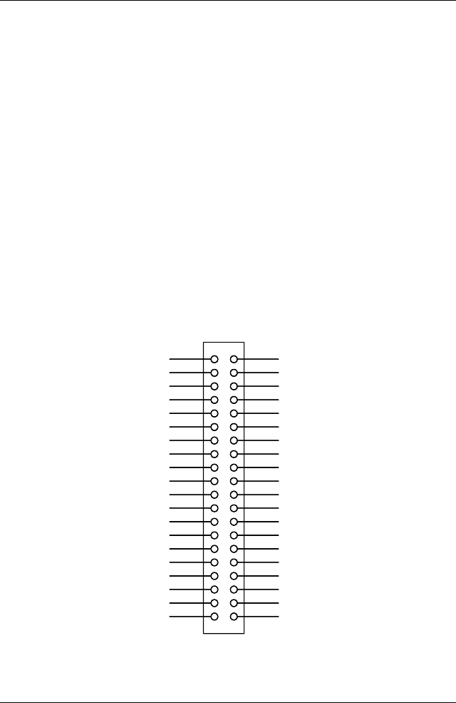
The PCI-7200 comes equipped with one 37-pin D-Sub connector (CN2)
located on the rear mounting plate and one 40-pin female flat cable header
connector (CN1). The CN2 is located on the rear mounting plate; the CN1 is on
front of the board. Refer section 2.4 PCI-7200‘s layout.
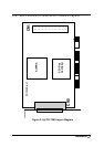
CN2 is used for digital inputs (DI 0 to DI 15) and digital outputs (DO 0 to DO 15)
The reminding digital I/O channels DI 16 to DI 31 and DO 16 to DO 31 are on
CN1. The pin assignment of CN1 and CN2 is illustrated in the Figures 2.2 and
2.3.
Legend:
DO n : Digital Output CH n
DI n : Digital Input CH n
GND : Ground
ACK : ACK handshaking signal
REQ : REQ handshaking signal
I_TRG: Input signal to start DI data sampling
O_TRG: Output signal can be controlled by software
21
20
2
34
56
78
910
11 12
13 14
15 16
17
19
22
23 24
25 26
27 28
37
18
29
35
3433
32
30
31
36
1
39 40
38
DI27
DI28
DI29
DI30
DI31
+5V
O_ACK
O_REQ
DI16
DI17
DI18
DI19
DI20
DI21
DI22
DI23
DI24
DI25
DI26
N/C
N/C
N/C
DO16
DO17
DO18
DO19
DO20
DO21
DO22
DO23
DO24
DO25
DO26
DO27
DO28
DO29
DO30
DO31
GND
O_TR1
21
20
2
34
56
78
910
11 12
13 14
15 16
17
19
22
23 24
25 26
27 28
37
18
29
35
3433
32
30
31
36
1
39 40
38
21
20
3
56
78
910
11 12
13 14
15 16
17
19
22
23 24
25 26
27 28
37
18
29
35
3433
32
30
31
36
1
39
38
DI27
DI28
DI29
DI30
DI31
+5V
O_ACK
O_REQ
DI16
DI17
DI18
DI19
DI20
DI21
DI22
DI23
DI24
DI25
DI26
N/C
N/C
N/C
DO16
DO17
DO18
DO19
DO20
DO21
DO22
DO23
DO24
DO25
DO26
DO27
DO28
DO29
DO30
DO31
GND
O_TR1
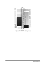
Figure 2.2 CN1 Pin Assignments