


INSTALLATIONS
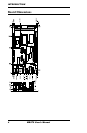
Connectors on MB879
The connectors on MB879 allow you to connect external devices such
as keyboard, floppy disk drives, hard disk drives, etc. The following
table lists the connectors on MB879 and their respective functions.
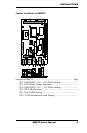
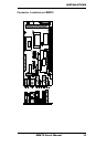
Connector Locations on MB879........................................................
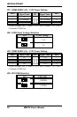
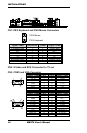
CN1: PS/2 Keyboard and PS/2 Mouse Connectors...........................
CN2: S-Video and RCA Connector for TV out................................
CN3: COM1 and VGA Connector....................................................
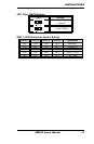
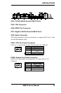
CN4: 10/100 LAN RJ-45 and USB1/2 Ports.....................................
CN5: 1394 Connector........................................................................
CN6: SPDIF Out Connector..............................................................
CN7: Gigabit LAN RJ-45 and USB3/4 Ports....................................
CN8: Audio Connector......................................................................
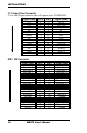
FAN1: CPU Fan Power Connector....................................................
FAN2: System Fan Power Connector................................................
J1: Floppy Drive Connector...............................................................
IDE1: IDE Connector........................................................................
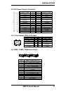
J2: ATX Power Supply Connector....................................................
J3: TV Out Header (RCA & S-Video)..............................................
J4: COM2, COM3, COM4 Serial Ports............................................
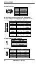
J5: IrDA Connector...........................................................................
J9, J6: LVDS Connectors (1st channel, 2nd channel)......................
J7: Panel Inverter Power Connector..................................................
J8: Digital I/O....................................................................................
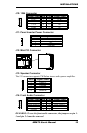
J10: 1394 Connector..........................................................................
J11: Panel Inverter Power Connector................................................
J12: Mini PCI Connector...................................................................
J13: Speaker Connector.....................................................................
J14: Front Audio Connector..............................................................
J15, J16: Serial ATA Connectors......................................................
J17: Wake On LAN Connector.........................................................
J18: System Function Connector.......................................................
J19: USB5 / USB6 Connector...........................................................
J20: CD-In Pin Header......................................................................
J21: Power LED Connector...............................................................
J22: Compact Flash Connector (solder side).....................................
PCI1: PCI Slot (supports 2 Masters).................................................
PCIE1: PCI-E(x1) Slot......................................................................
12 MB879 User’s Manual