


INSTALLATIONS
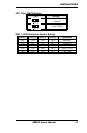
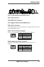
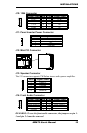
J10: 1394 Connector
Signal Name Pin Pin Signal Name
TPA+ 1 2 TPB+
TPA- 3 4 TPB-
+12V 5 6 NC
GND 7 8 NC
J11: Panel Inverter Power Connector
Pin # Signal Name
1 +12V (1A)
2 NC
3 Ground
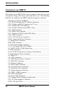
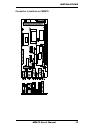
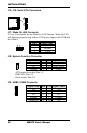
J12: Mini PCI Connector
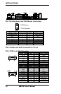
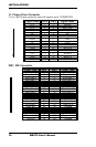
J13: Speaker Connector
The J15 connector supports 2W/8ohm stereo audio power amplifier.
Pin # Signal Name
1 Audio L
2 Ground
3 Ground
4 Audio R
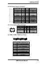
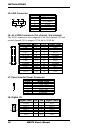
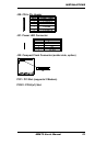
J14: Front Audio Connector
Signal Name Pin Pin Signal Name
Rear Audio R 1 5 Rear Audio L
Front Audio R 2 6 Front Audio L
Mic In 3 7 VREF Out
Ground 4 8
REMARKS: To use the front audio connector, the jumpers on pin 1-
3 and pin 2-4 must be removed.
MB879 User’s Manual 19