


Table of Contents
Introduction............................................................... 1
Product Description..............................................................1
Checklist...............................................................................2
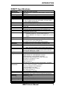
MB879 Specifications..........................................................3
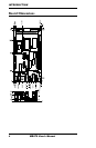
Board Dimensions................................................................ 4
Installations............................................................... 5
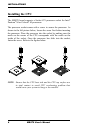
Installing the CPU................................................................ 6
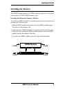
Installing the Memory...........................................................7
Setting the Jumpers.............................................................. 8
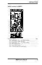
Jumper Locations on MB879................................................9
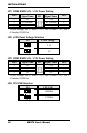
JP1: COM4 RS232 +5V / +12V Power Setting.................10
JP2: LVDS Panel Voltage Selection.................................. 10
JP3: COM3 RS232 +5V / +12V Power Setting.................10
JP4: CPU FSB Selection.....................................................10
JP5: Clear CMOS Setting...................................................11
[........................................................................................... 11
SW1: LVDS Resolution Switch Setting.............................11
Connectors on MB879....................................................... 12
Connector Locations on MB879.........................................13
CN1: PS/2 Keyboard and PS/2 Mouse Connectors............14
CN2: S-Video and RCA Connector for TV out................. 14
CN3: COM1 and VGA Connector.....................................14
.............................................................................................15
CN4: 10/100 LAN RJ-45 and USB1/2 Ports......................15
CN5: 1394 Connector.........................................................15
CN6: SPDIF Out Connector...............................................15
CN7: Gigabit LAN RJ-45 and USB3/4 Ports.....................15
CN8: Audio Connector.......................................................15
FAN1: CPU Fan Power Connector.................................... 15
FAN2: System Fan Power Connector.................................15
J1: Floppy Drive Connector................................................16
IDE1: IDE Connector.........................................................16
J2: ATX Power Supply Connector..................................... 17
J3: TV Out Header (RCA & S-Video)............................... 17
J4: COM2, COM3, COM4 Serial Ports............................. 17
J5: IrDA Connector............................................................ 18
MB879 User’s Manual iii