


2: Key Features & Components
User’s Manual
2•9
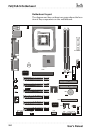
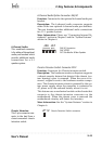
Drive Connectors
There are three drive connectors on the motherboard for
connecting IDE and floppy disk drives.
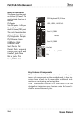
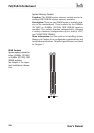
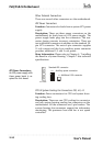
IDE Drive Connectors
Function: The two IDE connectors, marked ‘Primary’ and
‘Secondary’, are for connecting IDE drives to the
motherboard.
Description: The IDE controller on the motherboard sup-
ports IDE devices running in all modes up through ATA-
100. There are two IDE drive connectors. Each connec-
tor supports two drives, a ‘Master’ and a ‘Slave’ which
connect to the motherboard with a ribbon cable. The
supplied cable supports transfer modes through ATA-100.
More Information: See the section on “Connecting In-
ternal Peripherals” in Chapter 5 for instructions on con-
necting IDE drives. Technical specifications are listed in
Chapter 7.
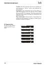
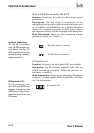
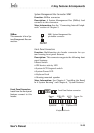
Floppy Disk Drive Connector
Function: The floppy disk drive connector, marked
‘Floppy’, is for connecting one floppy disk drive to the
motherboard.
Description: The floppy disk drive connector supports
connecting one floppy disk drive to the motherboard.
The ‘Floppy’ drive connector uses a standard FDD rib-
bon cable. The floppy disk drive connected to the end of
the cable will function as Drive A:. A second drive can
be added as Drive B: if required.
More Information: See the section on “Connecting In-
ternal Peripherals” in Chapter 4 for instructions on con-
necting a floppy disk drive. Technical specifications are
listed in Chapter 7.
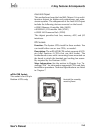
Secondary
Primary
IDE Drive Connectors
The channels are labeled
on the board.
Floppy Drive Connector