


P4D/P4D-N Motherboard
User’s Manual
6•4
Installing & Configuring An IR Port
There is a pin header connector for an Infrared commu-
nications port module on the motherboard. An IR port
enable wireless communication between the system and
another device with IR capability. Common examples of
such devices are a PDA or notebook computer. Installing
an IR port module requires disabling the COM2 serial
port on the rear I/O panel and reconfiguring it for IR use
in the CMOS Setup Utility.
Installing an IR port module requires an expansion slot
opening unless the system housing has a built-in IR port
with a cable to connect to the motherboard.
Follow the instructions that come that come with the port
module you want to install. The basic installation proce-
dure is as follows if the module installs in an expansion
slot opening:
1. Turn off and unplug the system if necessary.
2. Remove the system housing cover.
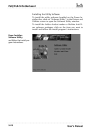
3. Locate the J45 IR pin header connector on the
motherboard. It is below the FDD connector.
4. Remove the expansion slot cover in the system hous-
ing that corresponds to an open PCI slot. There may
be a slot cover retaining screw to remove and put
aside for later use.
5. Insert the port module in the open expansion slot
cover and align the module’s mounting bracket with
the screw hole for the retaining screw If there is
one). Insert the screw and tighten it to secure the
port module in place.
6. Plug the module’s connector cable on to the IR con-
nector on the motherboard.
7. Replace the system housing cover.
8. Plug in and turn on the computer.
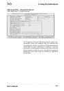
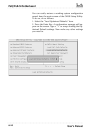
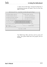
9. Run the CMOS Setup Utility and pen the Integrated
Peripherals section. Set the “COM2 Mode Select” to
the required mode, IrDA or ASKIR, and configure
the port settings below it if necessary. Save the set-
tings and reboot.