


Appendix B Pin Assignments
53
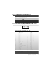
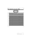
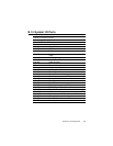
B.10 IR Connector (CN1)
Table B-10: IR connector (CN1)
Pin Signal
1 +5 V
2 N/C
3 IR_RX
4 GND
5 IR_TX
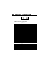
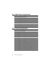
B.11 HDD LED Connector (CN4)
Table B-11: HDD LED connector
Pin Signal
1V
CC
2 LED
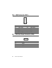
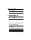
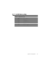
B.12 Power LED and Keylock Connector (CN2)
You can use an LED to indicate when the CPU card is on. Pin 1 of
CN2 supplies the LED's power, and Pin 3 is the ground.
You can use a switch (or a lock) to disable the keyboard so that the
PC will not respond to any input. This is useful if you do not want
anyone to change or stop a program which is running. Simply
connect the switch from Pin 4 to Pin 5 of CN2.
Table B-12: Power LED and keylock connector (CN2)
Pin Function
1 LED power (+5 V)
2NC
3 GND
4 Keyboard lock
5 GND