


PCM-3370 User’s Manual 20
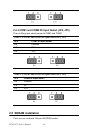
2.15 USB connector (CN26,CN27)
The PCM-3370 board provides two USB (Universal Serial Bus) inter-
faces which support plug and play and hot attach/detach for up to 127
external devices. The USB interfaces comply with USB specification
Rev. 1.1 and are fuse protected.
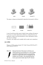
The USB interfaces are accessed through 10-pin (5x2) flat-cable connec-
tors, CN9. You will need an adapter cable if you use a standard USB con-
nector. The adapter cable has a 5-pin connector on one end and a USB
connector on the other.
The USB interfaces can be disabled in the system BIOS setup.
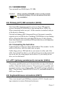
2.16 Reset Connector (CN1)
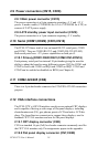
2.17 IR Connector (CN3)
PCM-3370F's IR is a 5pin boxheader. There is more detail pin assignment
at Appendix.
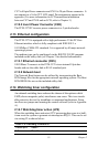
2.18 FAN Connector (CN4)
The PCM-3370F's FAN connector has speed detect and +5V power input.
It is a 3 pin connector for FAN.
2.18.1 Power Switch Connector (CN19)
There is a PCM-3370F 2-pin power switch at CN19.
2.18.2 Negative Power Input
PCM-3370F can have -5V and -12V negative power input from outside
power supply then it can drive stacking module -5V/-12V from PC/104
socket. It is a 3-pin box header.
2-3 IRQ11
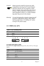
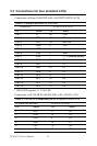
Table 2.7: Reset Connector
Pin Pin name
1Signal
2Gnd
Table 2.6: Watchdog Function J2