


ix
Content
Chapter 1 General Information ........................................2
1.1 Introduction....................................................................... 2
1.2 Features ............................................................................. 3
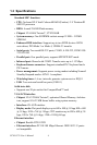
1.3 Specifications .................................................................... 4
1.4 Board Dimensions............................................................. 6
Figure 1.1:Board Dimensions (Component Side)...........6
Figure 1.2:Board Dimensions (Solder Side)................... 7
Chapter 2 Installation ......................................................10
2.1 Jumpers............................................................................ 10
Table 2.1:connectors and jumpers ................................ 10
2.2 Locating jumpers and connectors.................................... 12
Figure 2.1:Locating Connectors and Jumpers ..............12
2.3 Setting Jumpers ............................................................... 13
Figure 2.2:Locating Connectors (Solder Side).............13
2.4 CPU................................................................................. 14
2.4.1 CMOS clear (JP1)......................................................... 15
2.4.2 PCI VIO Select (JP3).................................................... 15
Table 2.3:PCI VIO Select (JP3).................................... 15
2.4.3 COM1 and COM2 RI Input Select (JP4, JP5)..............16
Table 2.4:COM1 and COM2 RI Input Select (JP4, JP5)..
16
Table 2.5:COM1 and COM2 RI Input Select (JP4, JP5)..
16
2.5 SDRAM installation........................................................ 16
2.5.1 SODIMM DRAM......................................................... 17
2.6 Primary (2.5") IDE connector (CN12)............................ 17
2.6.1 Connecting the hard drive............................................. 17
2.7 LPT1 (primary parallel port) connector .............(CN14)17
2.8 Keyboard/mouse connectors (CN17).............................. 17
2.9 Power connectors (CN15, CN18).................................... 18
2.9.1 Main power connector (CN15)..................................... 18
2.9.2 ATX standby power input connector (CN18)............... 18
2.10 Serial (COM1,COM2) (CN13,CN16)............................. 18
2.10.1 Primary(COM1:CN20/CN21,COM2:CN14/CN16).....18
2.11 COM2 422/485 (CN6) .................................................... 18
2.12 VGA interface connections............................................. 18
2.12.1 CRT display connector (CN8)...................................... 18
2.12.2 Flat panel display connector (CN7,CN20) ................... 18
2.12.3 Invert Power Connector (CN2)..................................... 19
2.13 Ethernet configuration..................................................... 19