


PCM-9387 User’s Manual 92
Appendix D AT/ATX Power setting
D.1 Introduction
PCM-9387 supports 2 kinds of power mode to boot up system. One is
ATX mode, the other is AT mode. ATX should connect standby power
and power supply on# signal to turn on main power supply. AT power
doesnít have those two pins and the pin 6 of PCM-9387 power connector
(CN3) needs to be connected to 5 voltage for properly boot up.
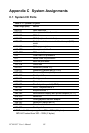
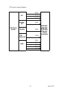
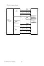
The power connector table & Power supply diagram tables are as bellow:
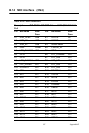
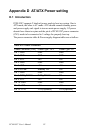
Table D.1: Power Connector
Power Connector (CN3) Power Type : ATX Power Type : AT
Pin 1: GND GND GND
Pin 2: GND GND GND
Pin 3: VCC +5V +5V
Pin 4: GND GND GND
Pin 5: VCC +5V +5V
Pin 6:VCCSB Standby +5V +5V
Pin 7: GND GND GND
Pin 8: PWR_PSON# PWR_PSON# NC
Pin 9: VCC +5V +5V
Pin 10: GND GND GND
Pin 11: VCC +5V +5V
Pin 12: +12V +12V(Optional) +12V(Optional)