


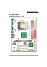
Mainboard PM945GC(V2.0)
12
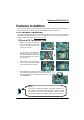
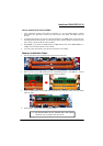
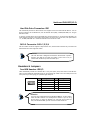
Hard Disk Drive Connectors: IDE1
The mainboards provide one IDE connector that supports Ultra ATA 33/66/100 IDE devices. You can
attach a maximum of two IDE devices, such as hard disk drive (HDD), CD-ROM, DVD-ROM, etc. using an
IDE ribbon cable.
In general, two IDE devices can be attached onto one IDE connector. If you attach two IDE HDDs, you
must configure one drive as the master and the other one as the slave. In this case, one optical device
i.e., CD-ROM, DVD-ROM…etc. should be attached to this connector as well.
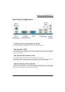
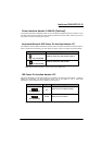
SATA II Connector: SATA 1/2/3/4
The four SATA II connectors support 3 Gbps transmit rate, and one SATA connector only can attach one
SATA HDD of each time using SATA cables.
Headers & Jumpers
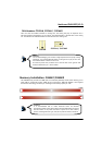
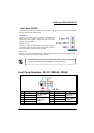
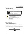
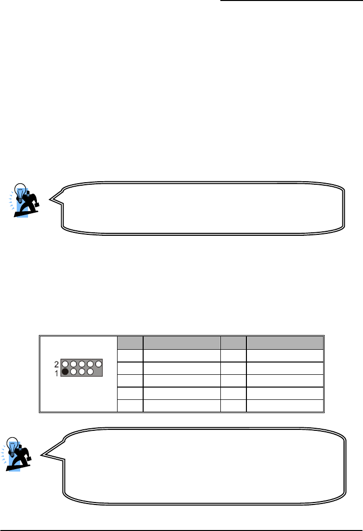
Front USB Headers: USB2/3
These mainboards provide four onboard USB 1.1/2.0 ports (back panel) that attach to USB devices.
There are two additional USB headers that can be connected by cables to four more USB ports on the
front panel of your case giving you a possible eight USB ports.
Pin Assignment Pin Assignment
1 VCC 2 VCC
3 -DATA 4 -DATA
5 +DATA 6 +DATA
7 GND 8 GND
USB2/3
9 Key 10 N/C
Attention
The FDD/ IDE cable is designed and should be attached with a specific
direction. One edge of the cable will usually in color such as red, to
indicate that should line up with the header pin-1.
Attention
If you are using a USB 2.0 device with Windows 2000/XP, you will need to
install the USB 2.0 driver from the Microsoft
®
website. If you are using
Service pack 2 (or later) for Windows
®
XP, and using Service pack4 (or
later) for Windows® 2000, you will not have to install the driver.