


Mainboard PM945GC(V2.0)
16
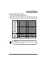
Power Supply Attachments
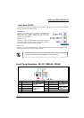
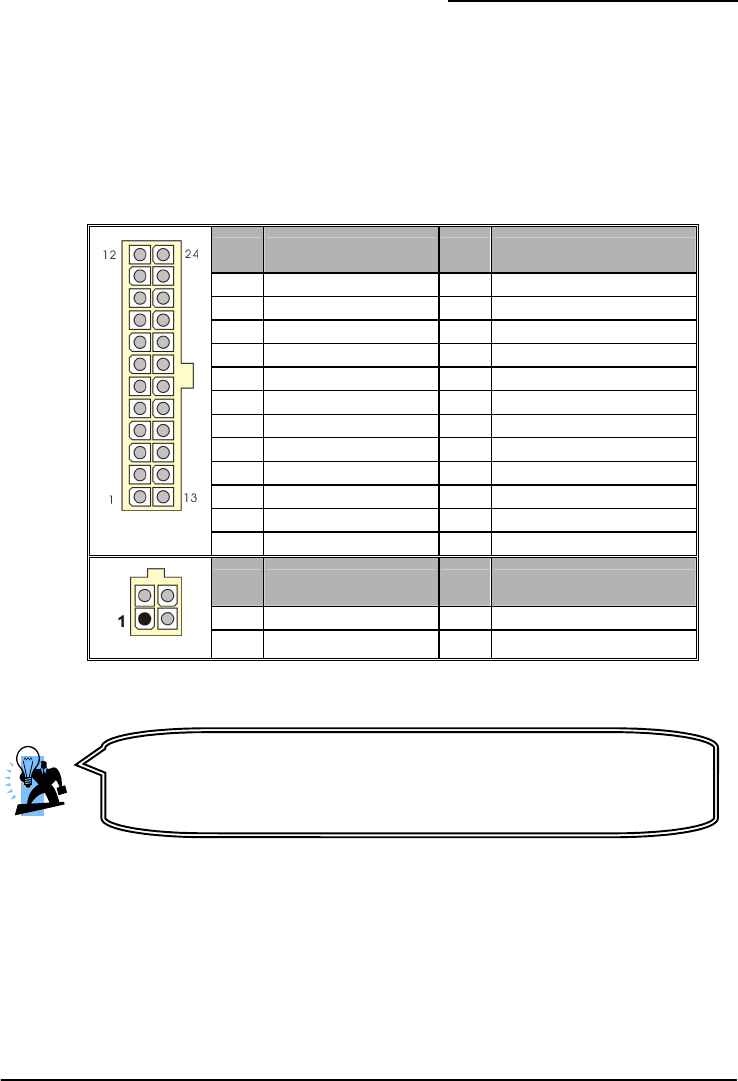
ATX Power Connector: ATXPWR, ATX12V
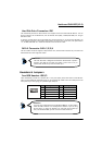
These mainboards provide two ATX power connectors, one 24-pin ATXPWR connector and one 4-pin
ATX12V connector. You must use a power supply that has both of these connectors and both connectors
must be attached before the system is powered on. These power connectors support several power
management functions such as the instant power-on function. The connector pins are described below.
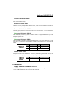
Pin Assignment Pin Assignment
1 +3.3V 13 +3.3V
2 +3.3V 14 -12V
3 Ground 15 Ground
4 +5V 16 Soft Power ON
5 Ground 17 Ground
6 +5V 18 Ground
7 Ground 19 Ground
8 PW_ON 20 -5V
9 +5V standby voltage 21 +5V
10 +12V 22 +5V
11 +12V 23 +5V
ATXPWR
12 +3.3V 24 Ground
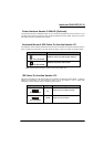
Pin Assignment Pin Assignment
1 Ground 3 +12V
ATX12V
2
Ground
4 +12V
A
ttention
In general, power cords are designed and should be attached with a specific
direction. The black wire of the power cord is Ground and should be attached
onto the header location of Ground.