


Chapter 2 Hardware Configuration
PMB-531LF USER
′
S MANUAL
Page: 2-13
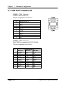
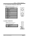
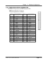
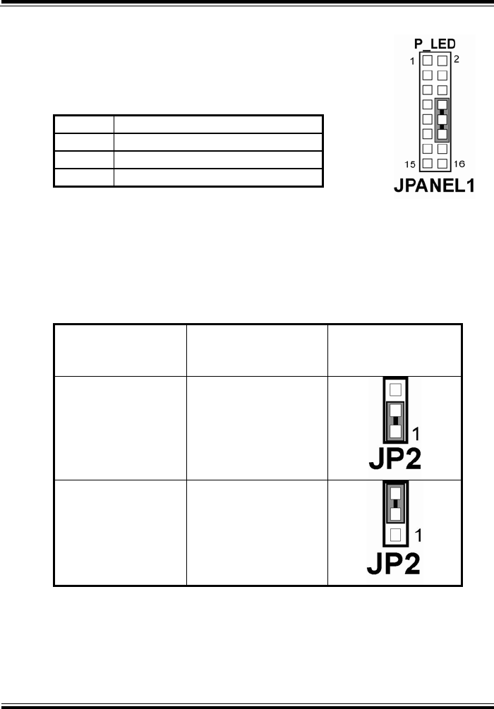
2-12. POWER LED CONNECTOR
JPANEL1 (8, 10, 12) : Power LED Connector
The pin assignment is as follows:
PIN ASSIGNMENT
8 PW_LED+
10 PW_LED+
12 PW_LED-
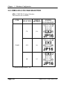
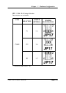
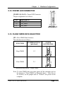
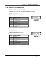
2-13. CLEAR CMOS DATA SELECTION
JP2 : Clear CMOS Data Selection
The selections are as follows :
FUNCTION
JUMPER SETTING
(pin closed)
JUMPER
ILLUSTRATION
Keep CMOS 1-2
Clear CMOS 2-3
*** Manufacturing Default – Keep CMOS.
Note: To clear CMOS data, user must power-off the computer and set
the jumper to “Clear CMOS” as illustrated above. After five to
six seconds, set the jumper back to “Normal” and power-on the
computer.