Chapter 2 Hardware Configuration
PMB-601LF USER
′
S MANUAL
Page: 2-19
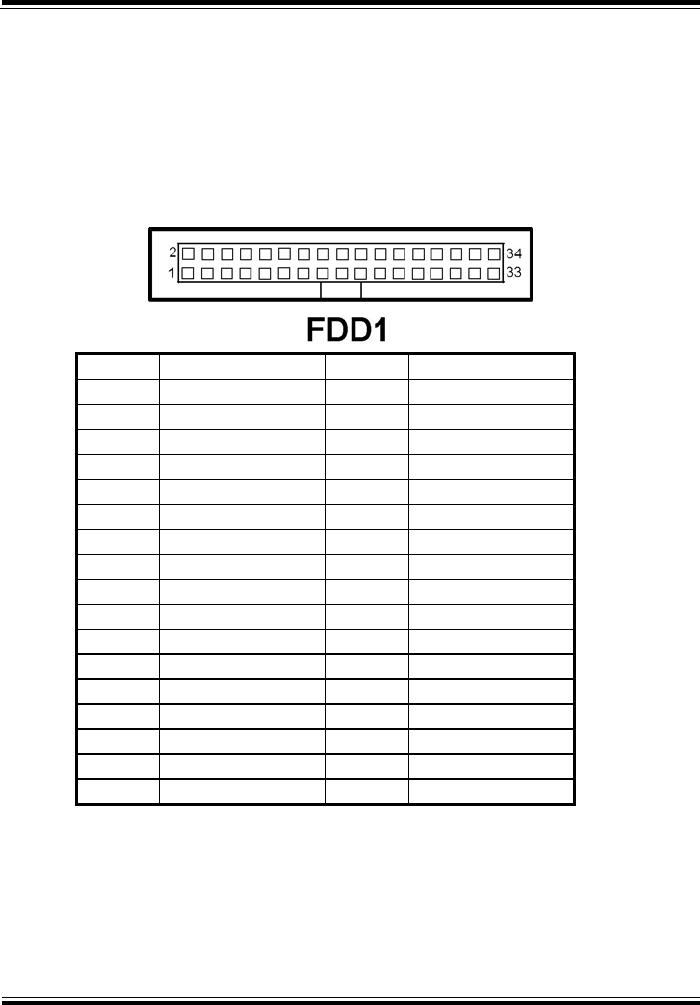
2-23. FLOPPY DISK DRIVE CONNECTOR
FDD1 : Floppy Disk Drive Connector
You can use a 34-pin daisy-chain cable to connect two-FDDs. On one
end of this cable is a 34-pin flat cable to attach the FDD on the board,
and the other side is attaches two FDDs.
The pin assignments are as follows :
PIN ASSIGNMENT PIN ASSIGNMENT
1 GND 2 F_DENSEL#
3 GND 4 NC
5 GND 6 NC
7 GND 8 F_INDEX#
9 GND 10 F_MTRA#
11 GND 12 F_DRVB#
13 GND 14 F_DRVA#
15 GND 16 F_MTRB#
17 GND 18 F_DIR#
19 GND 20 F_STEP#
21 GND 22 F_WDATA#
23 GND 24 F_WGATE#
25 GND 26 F_TRK0#
27 GND 28 F_WPT#
29 GND 30 F_RDATA#
31 GND 32 F_HDSEL#
33 GND 34 F_DSKCHG#


