


Intel Q965 Express Chipset—Development Kit Hardware Features
Intel
®
Q965 Express Chipset
DM October 2007
15 Order Number: 315664-002US
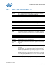
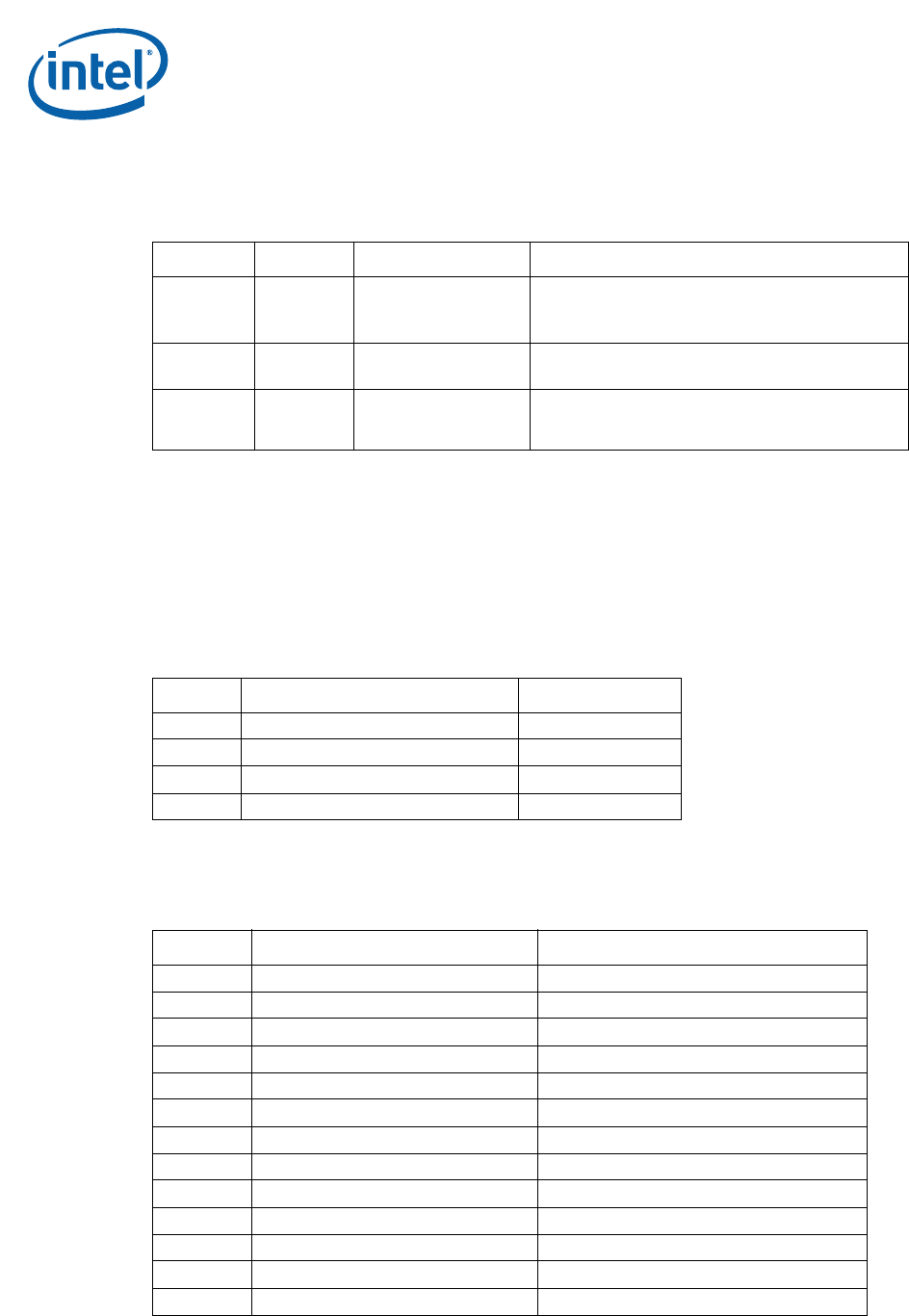
2.3.2 Jumper Settings and Descriptions
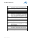
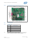
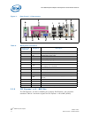
2.3.3 LED Descriptions
Power LEDs are on the board to indicate when standby and core power is being applied
to the planes. When on, they indicate that no devices should be inserted or removed.
Please refer to Figure 2 for the LED locations.
Caution: Inserting or removing devices when the Standby Power LEDs are on could result in
device or board damage.
2.3.4 Header and Connector Descriptions
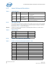
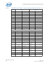
Table 5. Jumper Settings
Jumper Default Description Notes
J7LB 1-2 BIOS Config/Recovery
1-2 = Normal
2-3 = Config Mode
Off = Recovery
J6LB 1-2 Clear CMOS
1-2 = Normal
2-3 = Clear CMOS
J8LH 1-2 Power-On Forcing
1-2 = Normal
2-3 = Force On (Sets CPU presence bit; may not
always force board power on)
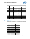
Table 6. LED Description
LED Description Notes
CR5BV 5-Volt Standby Power Display LED Green
DS1EV Port 80 Display – Right
DS2EV Port 80 Display - Left
CR7BV ME Enabled LED Red Blink
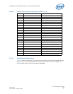
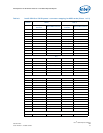
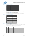
Table 7. Header and Connector Descriptions (Sheet 1 of 2)
Header Description Notes
J5LB Intruder Header
J7LH Serial Port Header
J3AU ATAPI CD Header
J7AU High Definition Media Interface Header
J8AU Front Panel Audio Header
J28LB Front Panel Header
J3TH CPU Fan
J4TH Chassis Fan
J5TH Chassis Fan
J2BV 2x12 Standard Power Connector
J1BV 2x2 12V Power Connector
J29LB Power LED header
J24LB SATA connector SATA HDD port 0