


Intel
®
Q965 Express Chipset
October 2007 DM
Order Number: 315664-002US 22
Development Kit Hardware Features—Intel Q965 Express Chipset
Note: +5 V Dual switches between +5 V and +5 V Standby depending on the current board
state.
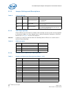
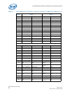
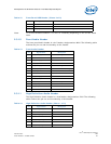
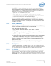
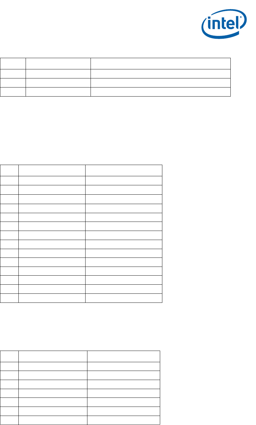
2.3.10 Front Audio Header
The front panel Audio header is a 2x7 header, designated as J8AU. The following table
outlines the pin out and functionality of this header:
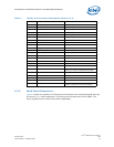
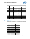
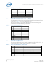
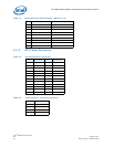
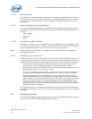
2.3.11 High Definition Audio Header
The High Definition Audio header is a 2x8 header, designated as J7AU. The following
table outlines the pin out and functionality of this header:
8 Ground
9 Key
10 USB_FP_OC0 Front panel USB over current signal (Ports 0,1)
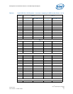
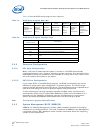
Table 12. Front Panel USB Header (Sheet 2 of 2)
Pin Signal names Description
Table 13. Front Audio Header
Pin Signal Name Description
1 AUD_PORT_1_R Port 1 Audio Right
2 GND Ground
3 AUD_PORT_1_L Port 1 Audio Left
4 AUD_FP_PWR Front Panel Audio Power
5 AUD_PORT_2_R Port 2 Audio Right
6 AUD_FP_RET_R Front Panel Audio Return Right
7 AUD_FP_JS Front Panel Jack Sense
8 No Connect Key Pin
9 AUD_PORT_2_L Port 2 Audio Left
10 AUD_FP_RET_L Front Panel Audio Return Left
11 AUD_VOL_UP Audio Volume Up
12 AUD_VOL_MUTE Audio Mute
13 AUD_VOL_DWN Audio Volume Down
14 GND Ground
Table 14. High Definition Audio Header (Sheet 1 of 2)
Pin Signal Name Description
1 AUD_LINK_BCLK_HDR
2 GND Ground
3 AUD_LINK_RST_HDR
4 VCC3 Power
5 AUD_LINK_SYNC_HDR
6 GND Ground
7 AUD_LINK_SDO_HDR