


Intel
®
Q965 Express Chipset
October 2007 DM
Order Number: 315664-002US 24
Development Kit Hardware Features—Intel Q965 Express Chipset
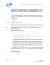
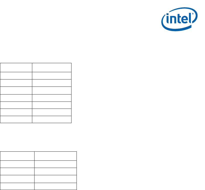
2.3.13 SATA Pinout
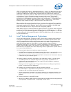
2.3.14 Fan Connectors
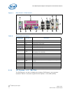
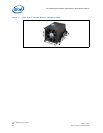
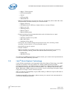
2.4 Thermal Considerations
The development kit is shipped with a BTX TYPE I heatsink/fan thermal solution for
installation on the processor. BTX systems are designed so that all the high power
components are in-line and can be cooled using a single, continuous airflow stream.
The BTX Thermal Module Assembly (TMA) provides airflow to the central processing
unit (microprocessor) and its voltage regulation (VR), which is located at the front of
the system, and then to the memory controller (G)MCH, Input/Output controller (ICH),
and the add-in card (AIC) in the first slot position. This same airflow supply pattern is
available in all BTX system designs.
The Thermal Module Assembly (TMA) consists of 4 main parts:
• The 92mm four-wire fan
• The plastic duct assembly (black)
• The heatsink (copper and aluminum)
• The metal retention clip (for holding the heatsink to the plastic duct assembly)
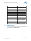
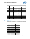
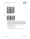
Table 17. SATA Pinout
Pin Signal Name
1 GND
2 TXP
3 TXN
4 GND
5RXN
6RXP
7GND
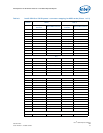
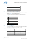
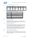
Table 18. Fan connectors
Pin Signal Name
1 GND
2 +12V
3 RPM
4 Control