


Intel
®
Q965 Express Chipset
October 2007 DM
Order Number: 315664-002US 16
Development Kit Hardware Features—Intel Q965 Express Chipset
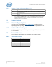
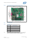
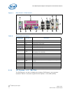
2.3.5 Back Panel Connectors
Figure 2 shows the location of the back panel connectors for boards equipped with the
8-channel (7.1) audio subsystem. The back panel connectors are color-coded. The
figure legend lists the colors used (when applicable).
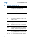
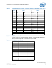
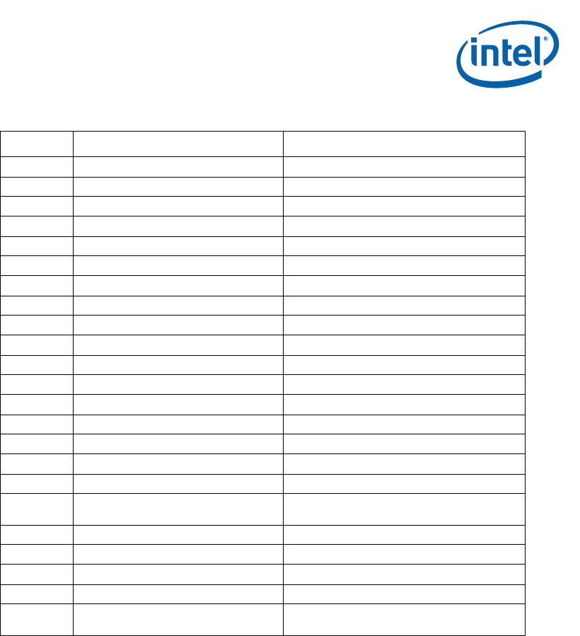
J22LB SATA connector SATA HDD port 1
J23LB SATA connector SATA HDD port 2
J21LB SATA connector SATA HDD port 3
J19LB SATA connector SATA HDD port 4
J20LB SATA connector SATA HDD port 5
J1MY DIMM connector Channel A DIMM 0
J2MY DIMM connector Channel A DIMM 1
J3MY DIMM connector Channel B DIMM 0
J4MY DIMM connector Channel B DIMM 1
J4LH Floppy connector
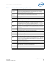
J6UB X16 PCI Express* Graphics slot For Graphics cards
J11LB X1 PCI Express slot PCI Express* port 4
J12LB X1 PCI Express slot PCI Express* port 5
J13LB PCI slot
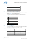
J14LB USB Front Panel Header
J15LB USB Front Panel Header
J16LB USB Front Panel Header
J1TM LPC BUS Header (TPM)
In order to Plug a TPM module into this
header, you must first disable onboard TPM
J1FW 1394a Front Panel Header Disabled
J2FW 1394a Front Panel Header Disabled
J9LB Power Button
J8LB Reset Button
J2BC XDP_SSA
This is reserved by Intel for debugging
purpose. Located at the back of the board
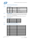
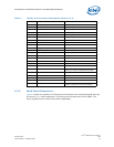
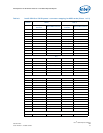
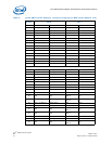
Table 7. Header and Connector Descriptions (Sheet 2 of 2)
Header Description Notes