


User Guide XB1 COM Express Module
©EKF -15- ekf.com
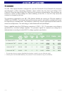
Main Memory
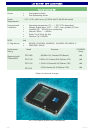
The XB1 COM Express Module is equipped with two sockets for installing 200-pin SO-DIMM modules
(module height = 1.25 inch). Supported are unbuffered DDR2 SO-DIMMs (V
CC
=1.8V) without ECC
featuring on-die termination (ODT), according the PC2-3200 or PC2-4200 specification. Minimum
memory size is 128MB; maximum memory size is 2GB. Due to the video requirements of the i915GM
chipset (some of the system memory is dedicated to the graphics controller), a minimum of 2x256MB
memory is recommended for the operating systems Windows NT 4.0, Windows 2000 or Windows XP.
The contents of the SPD EEPROM on the SO-DIMMs are read during POST (Power-on Self Test) to
program the memory controller within the chipset.
The i915GM chipset supports symmetric and asymmetric memory organization. The maximum
memory performance can be obtained by using the symmetric mode. To achieve this mode, two
SO-DIMMs of equal capacity must be installed in the memory sockets. In asymmetric mode different
memory modules may be used with the drawback of less bandwidth. A special case of asymmetric
mode is to populate only one memory module (i.e. one socket may be left empty).
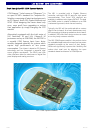
LAN Subsystem
The Ethernet LAN subsystem is comprised of the Intel 82573 Gigabit Ethernet controller, which
provides also legacy 10Base-T and 100Base-TX connectivity.
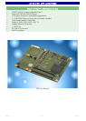
< Single PCI Express lane linkage
< 1000Base-Tx (Gigabit Ethernet), 100Base-TX (Fast Ethernet) and 10Base-T (Classic Ethernet)
capability
< Half- or full-duplex operation
< IEEE 802.3u Auto-Negotiation for the fastest available connection
< Jumperless configuration (completely software-configurable)
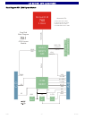
The NIC (Networking Interface Controller) is connected by a single PCI Express lane to the chipset
southbridge (ICH6). Its MAC address (unique hardware number) is stored in a dedicated EEPROM. The
Intel Ethernet software and drivers for the 82573 is available from Intel's World Wide Web site for
download (link provided on the EKF website).
By specification, the XB1 COM Express Module does not provide any I/O connector. Instead, the
carrier board must provide the RJ45 receptacle with integrated magnetics for copper twisted pair
Ethernet. All MDI (Media Dependent Interface) signals of the Ethernet PHY are routed to the
connector J-COM A-B.
The 82573 controller is connected to the PCI Express lane #3. As an alternate stuffing option, this
lane is available across the J-COM connector instead, for carrier board applications which require 4
PCIe lanes (typically configured as PCIe x 4 link). If this stuffing option had been ordered, no Ethernet
connectivity is provided on the XB1 itself, but may be replicated on the carrier board.