6
HARDWARE/CONNECTIONS
Model 503679
External
Antenna
Surge
Protector
HARDWARE/CONNECTIONS
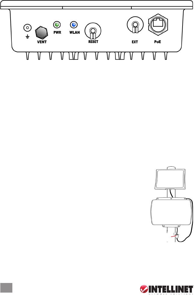
The components, connections and indicators depicted in the image (and directly
corresponding to the unit itself) are detailed below as they appear from left to right.
In addition, there are four holes on the rear panel of the device (the underside, as
shown here) for attaching either of the included mounting brackets.
Ground
Use the included ground wire to ground the device.
VENT
This special Gore membrane vent protects the device by allowing any water
moisture to escape while preventing excess moisture from entering. No
adjustments are necessary.
PWR
This LED lights green whenever the device is receiving power.
WLAN
This LED ashes blue during LAN activity.
RESET
To return any settings to factory defaults, unscrew the dust cap and press the
button for ve seconds or more.
EXT
If you require a higher-gain external antenna, unscrew the dust
cap and make your connection. The EXT connector features a
mechanical switch function that automatically disables the built-
in 9-dBi directional antenna and redirects the RF signal to the
external antenna. Conduct any signal alignment from the
external antenna. NOTE: Do not use the EXT connector for
any other purpose, as doing so could interfere with the
sophisticated mechanical switch inside the device. If the
cable used for an external antenna connection includes a
built-in surge protector, connect the shorter side of the cable to
the Wireless Super G Outdoor PoE Access Point and Bridge.
PoE
Unscrew the dust cap and connect the AP/bridge to the included PoE injector.


