


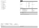
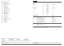
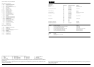
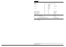

The following abbreviations are used to represent values for Control Module Pin-Out data
I Input PG Power Ground CAN CAN Network D Serial and Encoded Data
O Output SS Sensor / Signal Supply V SCP SCP Network V Voltage (DC)
B+ Battery Voltage SG Sensor / Signal Ground D2 D2B Network PWM Pulse Width Modulated
CAUTION: The information on this data page is furnished to aid the user in understanding circuit operation. THIS INFORMATION SHOULD BE USED FOR
REFERENCE ONLY.
NOTE: The characteristics listed are approximately those that can be expected at the control module connector pins with all circuit connections made and all
components connected and fitted.
Refer to the front of this book for detailed information and illustrations regarding the location and identification of harnesses, relays, fuses, grounds, control
modules and control module pins.
DATE OF ISSUE: December 2001
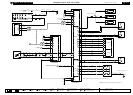
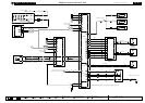
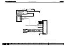
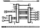
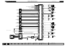
Fig. 16.5
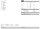
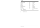
COMPONENTS
Component Connector(s) Connector Description Location
AUDIO CONTROL SWITCHES SW4 6-WAY / BLACK STEERING WHEEL
AUDIO UNIT ID1 2-WAY / BLACK INSTRUMENT PANEL CENTER
IP65 20-WAY / BLACK
IP106 2-WAY / COAXIAL
ROOF CONSOLE RC22 22-WAY / BLACK ROOF, CENTER FRONT
RC30 4-WAY / BLACK
RC31 2-WAY / BLACK
RC33 4-WAY / BLACK
RC34 6-WAY / BLACK
VOICE ACTIVATION CONTROL MODULE PH2 22-WAY / GREY TRUNK LH REAR
HARNESS IN-LINE CONNECTORS
Connector Connector Description Location
CA35 10-WAY / GREY / CABIN HARNESS TO ROOF HARNESS RH LOWER A POST
CA406 3-WAY / GREY / TELEPHONE HARNESS TO CABIN HARNESS BELOW LH REAR SEAT CUSHION
JB1 42-WAY / BLACK / JUNCTION BOX HARNESS TO ENGINE HARNESS ADJACENT TO LH SUSPENSION TURRET
JB129 22-WAY / GREY / INSTRUMENT PANEL HARNESS TO JUNCTION BOX HARNESS LH LOWER A POST
GROUNDS
Ground Location
G1 TRUNK / LH REAR
G14 ENGINE COMPARTMENT / REARWARD OF POWER DISTRIBUTION FUSE BOX
FOR CONTROL MODULE PIN-OUT INFORMATION, UNFOLD PAGE TO LEFT.
CONTROL MODULE PIN-OUT INFORMATION
Voice Activation Control Module
Pin Description and Characteristic
I PH2-1 MICROPHONE +
SG PH2-2 MICROPHONE SHIELD
B+ PH2-6 IGNITION SWITCHED POWER SUPPLY (II) (START / RUN STATUS)
B+ PH2-8 IGNITION SWITCHED POWER SUPPLY (I)
PG PH2-11 POWER GROUND
I PH2-12 MICROPHONE -
O PH2-14 D2B NETWORK WAKE UP
B+ PH2-22 BATTERY POWER SUPPLY
D2 CD4-1 D2B NETWORK RECEIVE
D2 CD2-2 D2B NETWORK TRANSMIT